I am currently testing the capabilities of uwb and using dwm1001-dev. I want to use 1 anchor (initiator) to communicate with 4 tags (responder) through SS-TWR and get the distance of each tag. I want to light up a led if a tag has moved 2cm or more from its original position. I am new to this, so we are currently using the Decawave/dwm1001-example (youtube), Decawave DWM1001 Firmware User Guide, Decawave DWM1001 Firmware API Guide, Decawave DWM1001 System Overview, Decawave APS011 Application Notes (Source of error in TWR), and Decawave APS013 Application Notes (Implementation of TWR) as a bench mark. I do understand the standard PANS library is meant to use multiple anchors to get a better estimate of the tags distance, but I want to test the limits of UWB with just one anchor. I am able to make 1 anchor communicate with 1 tag using SS-TWR, but I am getting a distance fluctuation of ±20cm when the anchor and tag are 1m apart (0.8m – 1.2m) in an open field, vertically oriented. I have tried these ways to lessen the error margin:
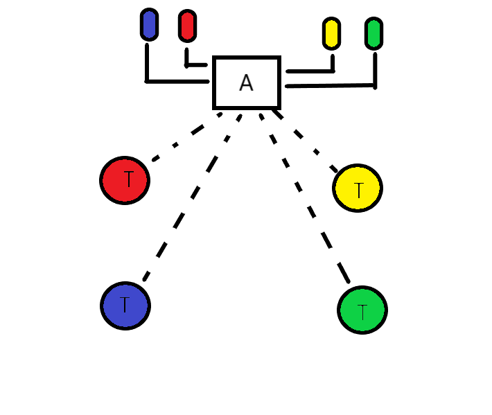
I am still getting a ±20cm fluctuation with these changes. I am aiming for an accuracy of <2cm. I know the equation in the code for calculating time of flight and distance is correct, but I think the clock difference between the anchor and tag is affecting the ToF calculation. The diagram below is what I am trying to achieve.
I would like to think that the system I’ve put together is at the higher end of the accuracy limits, we can achieve a 2cm (1 sigma) point to point range accuracy from 50 cm to 40 m, as verified using optical survey equipment. When you get to that level of accuracy you need to start worrying about the accuracy of your “truth” measurement.
We however do that by combining 5 double sided TWR measurements. It’s not a simple mean of 5 ranges because we also do some outlier rejection filtering.
Our individual TWR measurements have a standard deviation of around 3 cm under ideal conditions so you need to do some averaging to get the noise down.
We apply system wide temperature and signal power corrections in addition on unit specific antenna calibrations. To the first order temperature effects are fairly linear but there are some smaller non-linear effects that seem to follow very different patterns on every unit. We do say that antenna calibration should ideally be done within 10 C of the planned operating temperature to minimise the impact of these effects.
This was all using DS-TWR with a total time for the full cycle of around 1.25ms, we kept the time as short as possible to minimise clock drift during the ranging process.
I did post some numbers here on this a while ago comparing SS and DS performance. The TL:DR is that under good conditions (well within range so signals we nice and strong) there wasn’t any significant difference in performance. However at longer ranges I’d expect the clock rate measurement to be a little less accurate and so the performance to drop off faster in SS then DS.
To answer your questions as best I can:
No idea, didn’t use either.
Yes I believe so, it needs to do this to calculate positions so you run it as if it’s calculating positions and get it to output the measured ranges. PANS is closed source, you can’t measure it.
Yes. But only by making use of averaging and only with a certain confidence level.
Rates of drift - you have to calculate that yourself. But you can get the current difference in the clock rates, which is all you need to know, by reading Sub-Register 0x27:28 – DRX_CONF:DRX_CAR_INT
Yes, I’m surprised it works at all without doing this. With DS TWR you don’t need to worry about clock differences, they cancel out. With SS you need to allow for them to get any level of accuracy.
If you know the clock differences then when subtracting the anchors Rx to Tx delay you need scale that delay by the clock difference.
What matters is the average difference in the clock speeds over the time taken to measure the range. What you can measure is the clock difference when you receive a packet. So difference has a big impact, drift rate has a lesser impact but over long periods could make a difference.
By measuring it. If you get a constant error in range then that’s your bias. Also remember when scheduling the transmit time of the anchor you need to allow for the transmit antenna delay time.
The correct one for each unit. Set the system to output a constant carrier (see the user manual/app notes for how to put it into this special mode). Give it time to warm up and stop drifting. Measure the frequency on a spectrum analyser. Adjust the trim to get the output as close as possible to the correct frequency. The DWM1001 should come with a factory set trim for that unit stored in the OTP memory.