Hi,
Thanks for the questions and sorry for the delay.
-
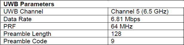
What is the network configuration used by PANS and compatible with the factory antenna calibration stored in the OTP? Is it the one shown in Table 1 of the DWM1001 System Overview document?
Yes it is. Listed below.
-
This gave me the following value: 0x404C404C
Is the factory calibrated antenna delay equal for both TX and RX? And in this case it seems to also be equal in PRF 64 and PRF 16 mode? ?
The module is tested with MDEK factor software and is implanted with single-sided TWR algorithm. The TX and RX delay portion in such algorithm is the same. Thus, the calibrated delay is evenly divided into TX and RX with the same value.
As listed in the answer to Question 1, the embedded software only uses PRF 64. Thus the PRF16 config options are not considered. i.e. the antenna delay of PRF16 is not calibrated. There are still space in the OTP to be used for PRF16. So, if necessary, the DWM1001 module can be further calibrated for PRF16 by the customer. -
Why am I observing a 25-30 cm distance bias/error when the factory calibrated antenna delay is used? This appears independent of whether the TX/RX preamble code is set to 10 or 9 (see other question below).
There can be various reasons. You may need to check (but not limited to) reasons below:- whether both devices in your ranging are calibrated;
- whether range bias is applied;
- whether the response time is too long.
-
a. Why is Channel 5 being used in the DWM1001 examples while Channel 2 is used in the DWS1000 examples? This does however align with Table 1 (as mentioned above).
The DW1000 chip itself is supports various configurations, including different channels (1,2,3,4,5,7). The DWS1000 has DWM1000 module on it. Similar to EVK1000, DWS1000 supports all channels that DW1000 does. The examples aims to show how to perform each individual functions that the chip is capable of. It can choose any channel, with any configuration that works.
MDEK1001 (DWM1001) is a product with software and is targeting specific use case with specific configurations. It has antenna specifically designed for channel 5. All tests around the DWM1001 module are based on the configuratiosn listed in the answer of Question 1. using other configurations can lead to unexpected performance.b. Why is the TX/RX preamble code 10 used in the DWM1001 examples instead of 9 which used in the DWS1000? In this case Table 1 (as mentioned above) defines it to be 9!
see answer to 4.ac. Why is the RX timeout set to the maximum (65 ms) instead of an actual/expected microsecond-ranged value?
Yes you are right. The 65 ms timeout in the example is too long and is not necessary. Please tailor the timeout values according to the actual/expected values in your design.d. Why is POLL_TX_TO_RESP_RX_DLY_UUS set to 100 us in the DWM1001 example and to 140 us in the DWS1000 example? In general, why is this value set so low, given that POLL_RX_TO_RESP_TX_DLY_UUS is already larger than this (330 us in DWS1000 example, 1100 us in DWM1001 example)? Shouldn’t this delay of the response (in the responder) be accounted for in the transmitter? Or at the very least be accounted for in RESP_RX_TIMEOUT_UUS which in the DWS1000 example is only 210 us?
The POLL_RX_TO_RESP_TX_DLY_UUS indicates the time interval between POLL RX Timestamp (RMARKER) and the RESP TX timestamp (RMARKER). The length of the timings should follow the below:
POLL_TX_TO_RESP_RX_DLY_UUS + Preamble_length + SFD + PHR + Payload_length < POLL_RX_TO_RESP_TX_DLY_UUS
In the DWS1000 example, there is:
POLL_TX_TO_RESP_RX_DLY_UUS + 128 + 8 + 21 + 15 < POLL_RX_TO_RESP_TX_DLY_UUS
Here the POLL_TX_TO_RESP_RX_DLY_UUS = 100 is almost optimized.
In the DWM1001 example, the timings can be improved for better performance.
e. Why don’t you have any responder example with interrupt? I would expect the responder to be the most time-critical application given that the response transmission timestamp is based on the receive timestamp.
The simple examples only aim to show the very basic implementations of each individual features. They are kept as simple as possible for easy understanding. You can implement interrupt in your own design.f. Why is the bias correction, dwt_getrangebias, not applied in any of the examples?
There is no simple example of the usage of this function. There is usage of it in https://www.decawave.com/wp-content/uploads/2018/09/evk1000_software_package_v1.1.zip
evk1000_software_package_v1.1\DecaRanging_App_3.05\Source Code\DecaRangingCustomerMP_source_code_rev3p05_vcxproj\application\instance_log.c
Line 174
In short, when using it, you do:
distance = raw_distance - dwt_getrangebias(ch, raw_distance, prf); -
So why the heck is UUS_TO_DWT_TIME set to 65536?
As was mentioned in the code comment, uus indicates UWB microsecond, not microsecond. In calculation, 1 uus is around 1.025 us. -
Why does the data rate and/or preamble length affect the delay configuration of delayed transmissions?
As was mentioned in answer 4.d, the value of POLL_RX_TO_RESP_TX_DLY_UUS should consider preamble_length and payload_length too. In your configuration here, the data package is quite long. Taking 20 bytes payload as example, there is preamble_length ~ 4096us, PHR ~ 172us and payload_length ~ 1707us.
Please refer to IEEE Std 802.15.4™-2015, section 16. HRP UWB PHY for detailed calculation of each field in the data frame. -
Should I expect a better range accuracy and performance with PANS? Or should I be able to achieve the same, although in a less straight forward (out-of-the-box) way with the plain library?
The PANS system have taken the calibration info, the range bias and some power compensation factors into the operations. I’d expect similar perfromance if your software design based on “plain examples” have all these factors included too.
Best Regards,
Weibo