I’ve learned that increasing the response time of ss-twr leads to more ranging errors based on forum discussions. I’m particularly interested in clarifying the following questions:
Is the error caused by clock drift? If so, can the ranging result be corrected using the carrier integrator?
Why does modifying the code in the ss-twr example to use system time result in significant errors in distance measurement? I measured a value of 200cm, whereas the example shows only 112cm.
’
uint32_t reply_time = dwt_readsystimestamphi32();
/* Compute final message transmission time.*/
uint32_t resp_tx_time =
(reply_time + ((1000 * UUS_TO_DWT_TIME) >> 8));
dwt_setdelayedtrxtime(resp_tx_time);
’
The configuration I used was: channel 2, PRF 64 MHz, 6.8Mbps, Preamble 64, SFD 8, the antenna delay is default value in SDK, which is 16456.
The experimental environment is an open and flat field, there are only two nodes.
The nodes positioned at a height of 1.58 meters. The communication between nodes is line-of-sight.
Thank you for taking the time to read this, and I appreciate your early response in advance!
Single sided ranging is:
A sends to B.
B waits a fixed time and then replies to A.
A receives the reply.
Distance is calculated based on the time taken for the signals to travel from A to B and back divided by the speed of light.
Signal travel time = (A receive time - A transmit time) - Fixed time delay.
But the time (A receive time - A transmit time) is measured on the clock of unit A.
The fixed time delay is measured on the clock of unit B.
While ideally the two clocks will be running at the same rate they will always have a small difference in speed. So to get correct answer you need to do:
Signal travel time = (A receive time - A transmit time) - Fixed time delay * Ratio of Clock A to Clock B
“Ratio of Clock A to Clock B” will be very close to 1, it will be off by maybe 10 parts per million (somewhere between 0.99999 and 1.00001). For most things such a small error isn’t significant enough to worry about. But light travels very fast, the travel time will be tiny in comparison to the fixed time delay (for 112cm it will be around 0.004 microseconds). This means even a small error in that clock ratio correction will start to result in a significant error in the calculated travel time.
The error will be proportional to the fixed delay and so a shorter delay will introduce a smaller error.
The carrier integrator is a way of measuring the clock difference between the two UWB devices. This allows you to calculate the correct clock ratio to scale the time delay by and so obtain a more accurate distance. However it’s never going to be perfect, it will get rid of most of the error but not all of it. This is why shorter delays are still good, all things being equal a shorter delay still gives a smaller error.
Reading the system time will give you the time when that line of code runs. Which will be some unknown length of time after the packet has been received. How long after will be dependent on your code and processor. The whole system assumes the reply is sent an exact amount of time after the initial message is received, if you use some random time based on when your system gets around to running a specific bit of code then your delay will be both larger than expected and inconsistent.
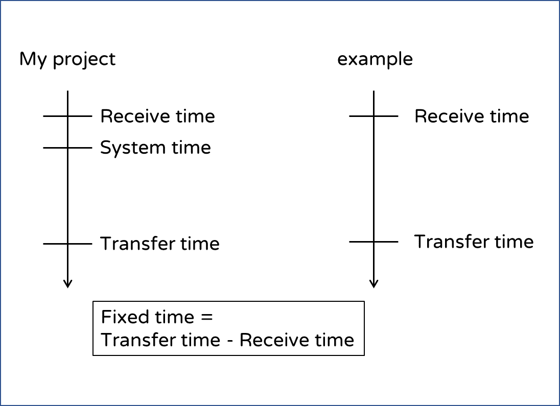
Based on the diagram, it appears that this delay has been extended somewhat. However, in my equation, I subtract the receive time from the transmit time rather than calculating it based on a fixed delay.
Perhaps it aligns with your statement, ‘The error will be proportional to the fixed delay, and so a shorter delay will introduce a smaller error.’
Does this mean that a longer delay is causing increased delay and error?
I don’t completely follow what you are doing or why system time should ever be part of this calculation.
The reply transmit time (Transfer time in your diagram) is normally set by the unit sending the reply by adding a fixed amount on to the receive time value. This is because the unit that receives the reply and calculates the distance needs to know what the delay in the other unit was. If it’s constant then knowing the delay is easy.
You could instead set a transmit time to be at any point in time that you want, calculate the delay as (transmit time - receive time) and then include the delay used in the message. But this is adding complexity to the system without adding any significant benefits.
Or you could instead either transmit the message as quickly as possible (instant transmit rather than timed transmit) and then calculate the delay based on (transmit time - receive time). This gives the shortest possible delay but only the system sending the reply would then know this time, not the one calculating the distance. So at that point you’d either need to send a second radio packet with what that delay was or use some other non-UWB method to transfer that information.
If the delay is twice as long then the error caused by incorrect correction of the clock delays will also be double. However assuming you can keep the delays under 1 ms and are correctly applying the carrier integrator correction then the errors caused by this effect become insignificant in comparison to the other errors in the system.