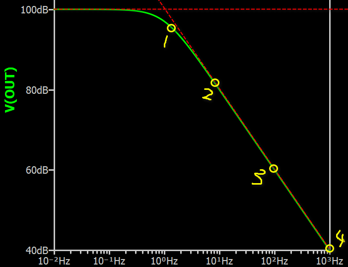
Consider where you put your marker. In control theory, red line called asymptote. A pole give -20dB/decade, which is refer to this asymptote. In old age, control engineer don’t have computer program to plot a transfer function, therefore, they use asymptote to draw bode for approximation. @bordodynov already shown you in his example that, by setting two markers further away from the pole, it can give you -20dB/decade. You think at 10Meg to 100Meg is linear but it is NOT!!! Your eye just cannot differentiate that 1dB different at 10Meg in that exact function.
(this plot not your simulation but you are just similar in measuring marker 1 and 2 but you think it already with slope like 3 and 4)
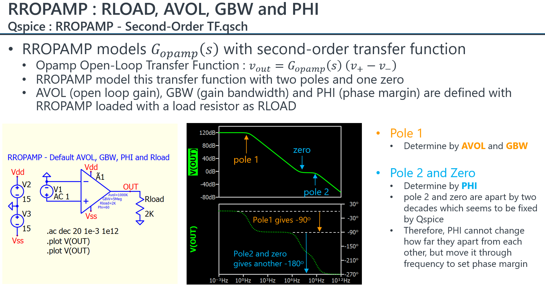
I saw you setting the PHI to 90 in your example. I performed more tests to study this device frequency characteristic.
For PHI, my major observation and advise are
PHI is limited between 0 to 90 degree
Be very careful PHI=0. Like some Qspice instance parameter, setting it to 0 may force a default value or something else. My test suggests setting PHI=0 (or negative number) will force PHI to default, which is 60 degree. To test PHI at 0, just put a very small number. PHI>90 will limit to 90.
PHI control frequency of a pole/zero pair, but how far this pole/zero apart, user seems have no controllability (always two decades).
If you find anything not following these, let me know and I will correct my understand.
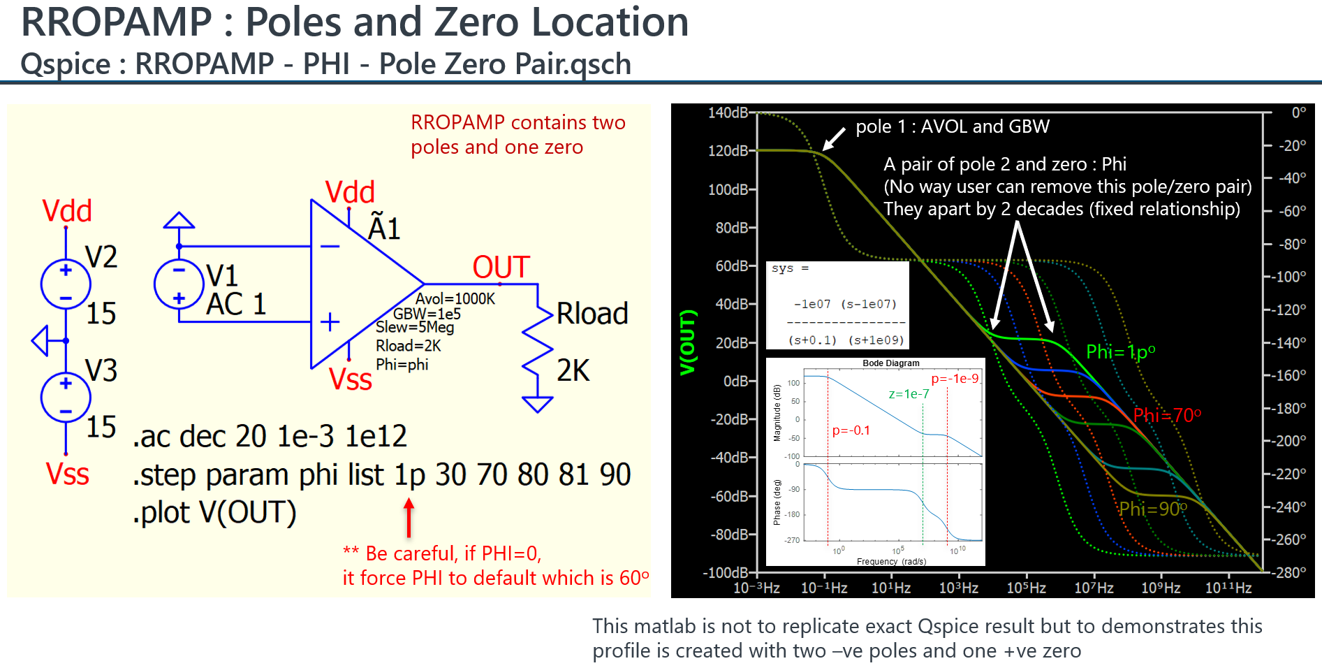
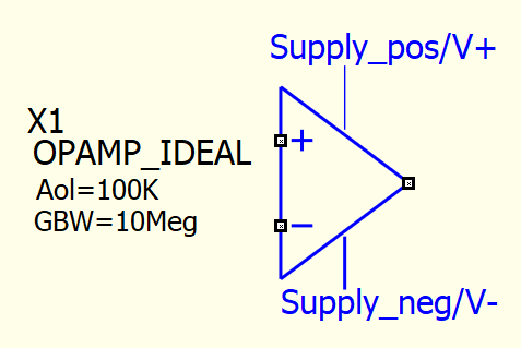
Kelvin, Can you update/add in your github qspice models this kind of op-amp with positive and negative supply voltage on itself in order to account also for saturation?
I mean to have also this kind of op-amp with supply voltage on itself, and not to add again and again the limitter after op-amp ideal that you made some time ago. OP_AMP with negative and positive supply.qsch (7.2 KB)
Some kind of below op-amp symbol:
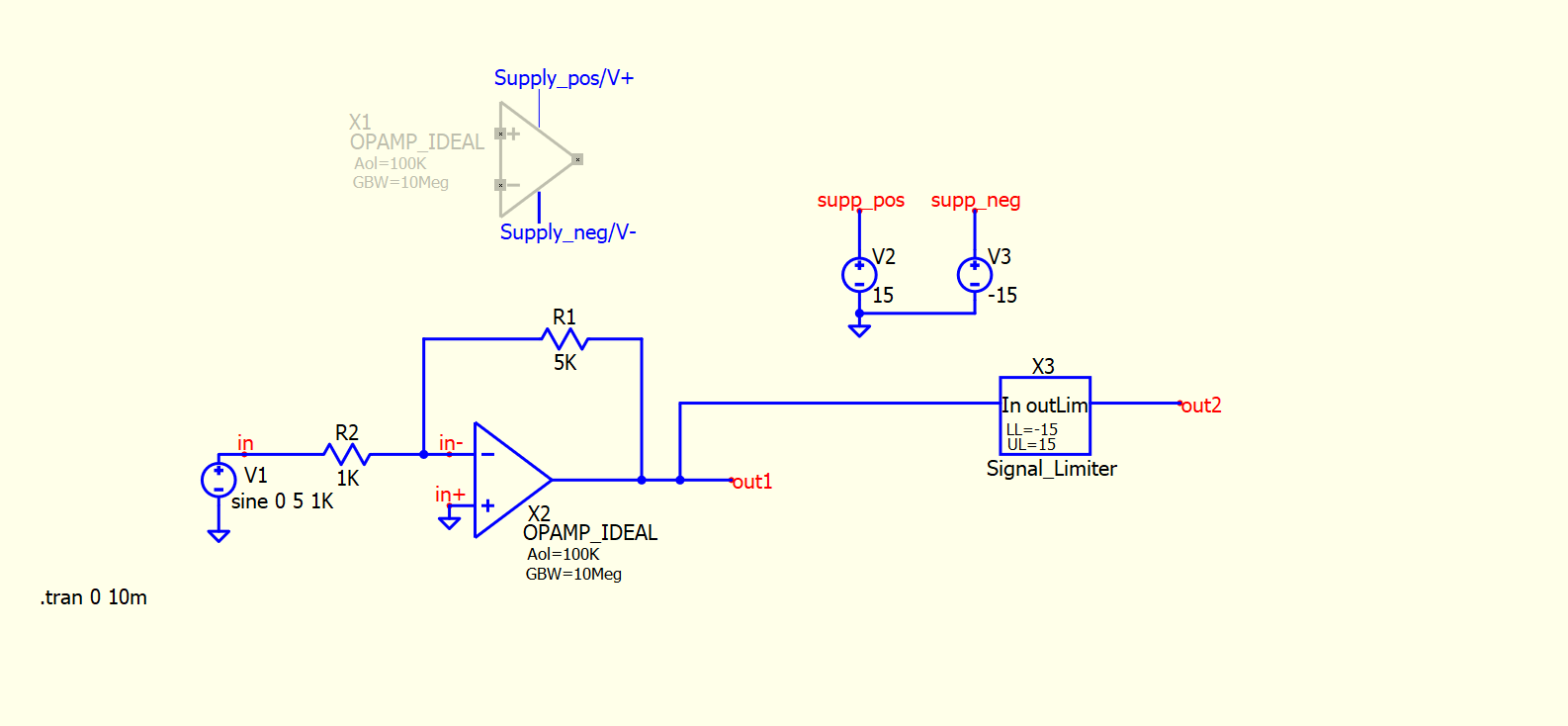
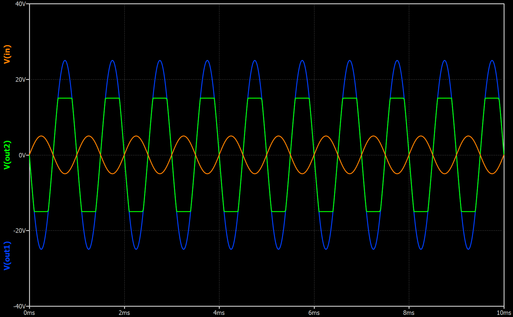
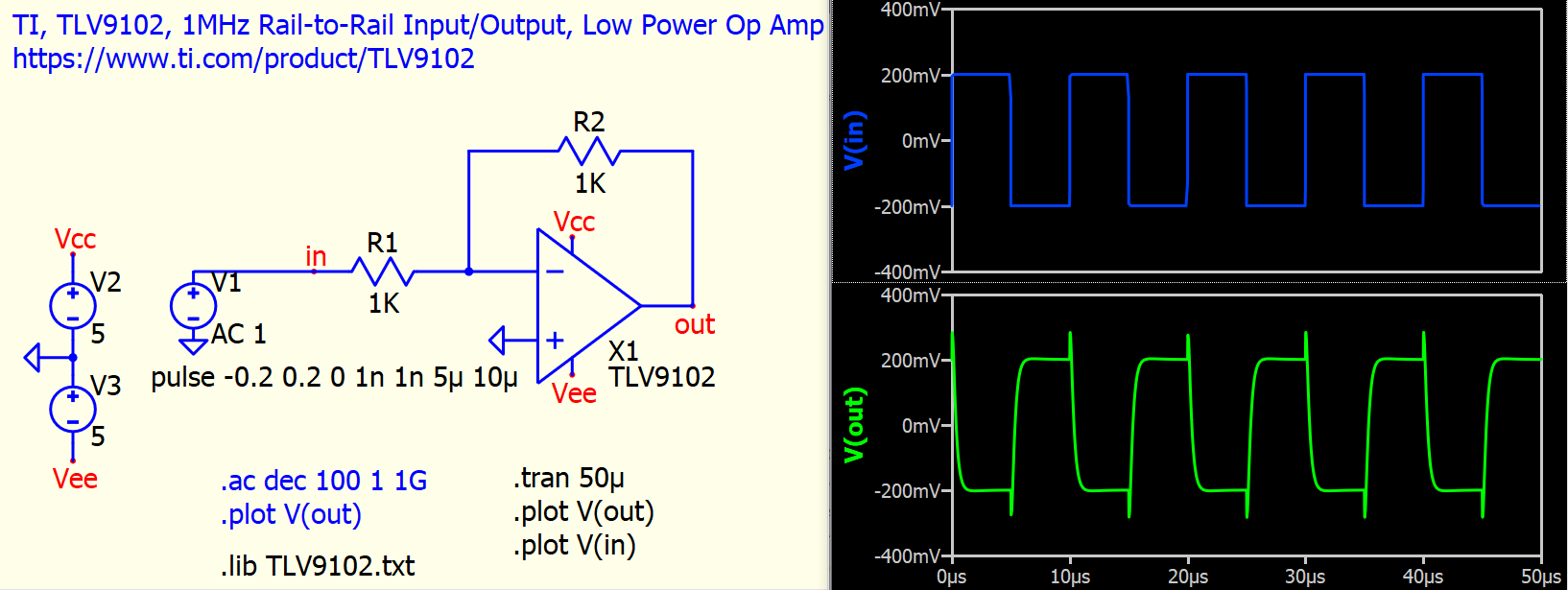
I am unsure about the best approach to limit the output voltage of this single-pole op-amp model in LTspice.
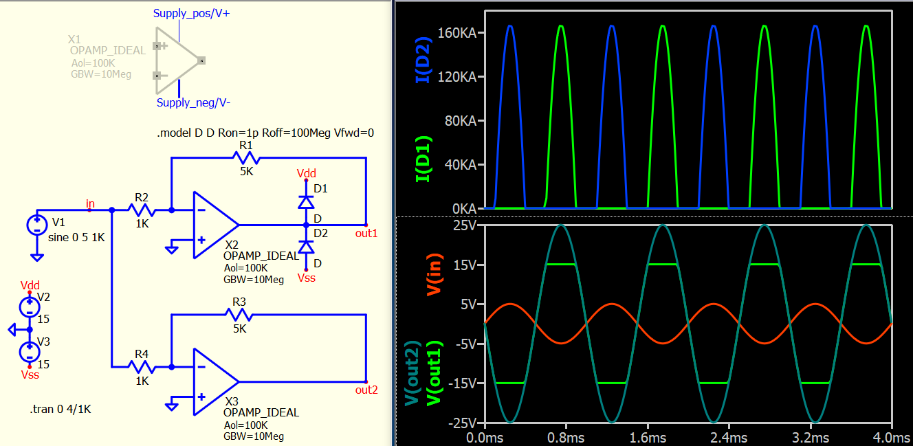
One possible approach is to use a diode to limit the output, but it is important to consider that the power supply would experience significant current during the output voltage clamp. I can create a symbol for this model and embed the voltage source within the symbol. Using an external source may not be meaningful for this type of behavioral model, as the current does not represent anything specific. I can assign input parameters for the upper and lower output rails. However, I am uncertain if this is the proper method to achieve the desired output voltage limitation. Let’s see if anyone can suggest a best-known method for implementing output voltage limiting in a single-pole op-amp.
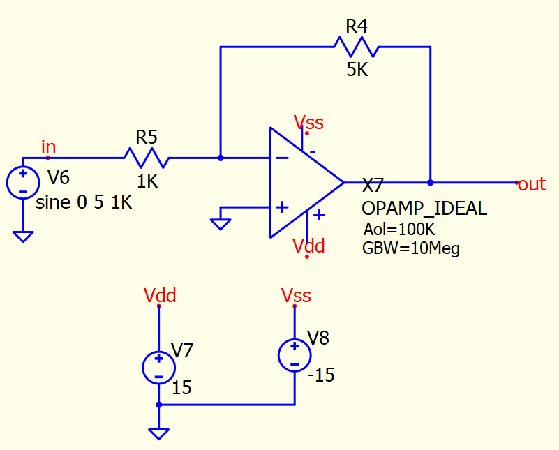
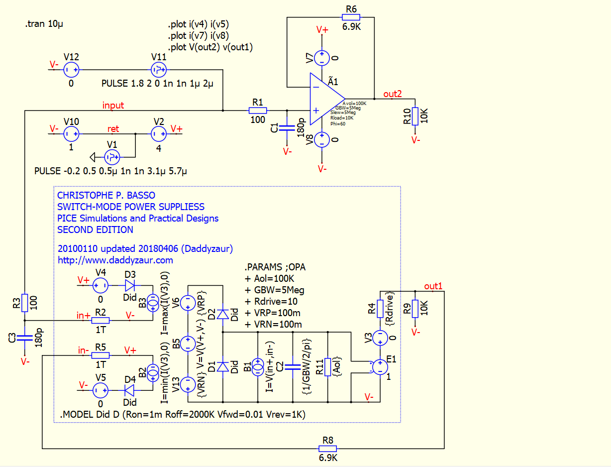
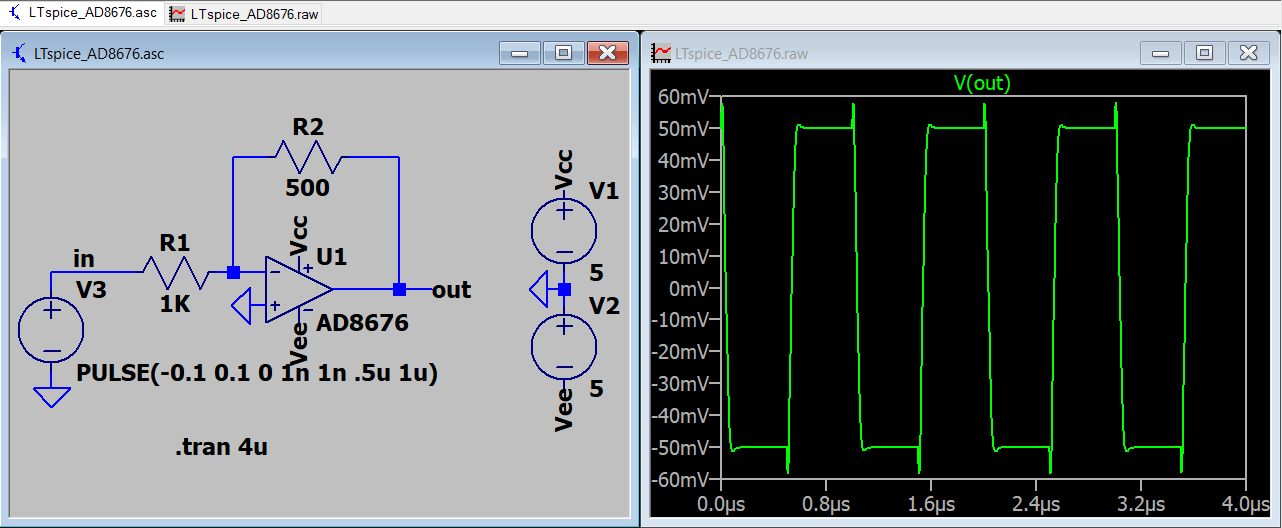
@Cornel ,@KSKelvin, you can use this QSPICE model, attached. I put together this little test simulation to show a nasty bug on IP analog models that are messing up both the output and the rail currents. test_005.qsch (28.8 KB)
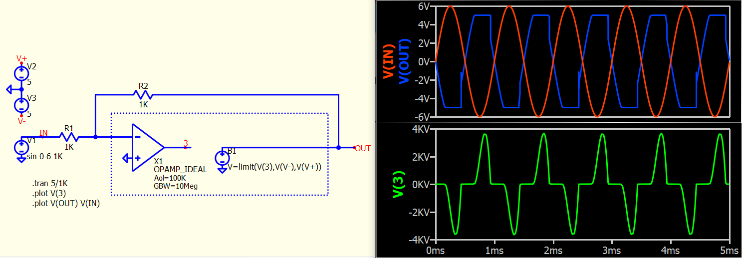
Possibly, you haven’t tested your idea as it is not a proper way to achieve the desired outcome. Here is a demonstration for your reference. In your previous post, you placed the limiter after the op-amp circuit. However, if you integrate the limiter as part of the op-amp, you won’t achieve the desired result. That’s why I use a diode clamp.
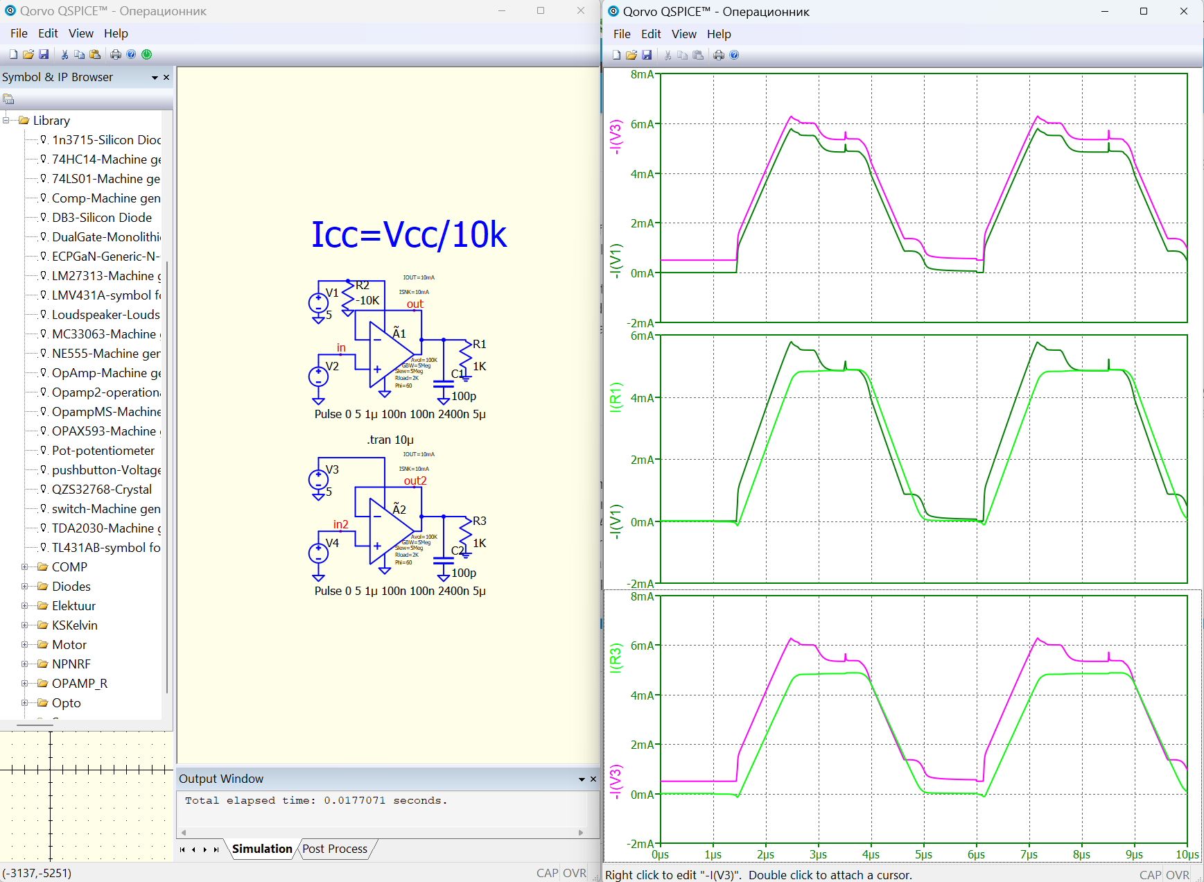
@Cornel ,@KSKelvin, all problems you are taking about are solved in the model I provided. You have very accurate power rail currents, perfectly matching the output currents. There are no abnormal currents/voltages levels. It is behaving VERY MUCH like a real opamp. Give it a try and let me know if you see any issues, I will try to fix them.
There are many modeling techniques and methods, and I must admit that I am not an expert in opamps. The latest discussion with @Cornel is about his request to add an output voltage limit to the single-pole opamp model, which is derived from the LTspice symbol opamp and the opamp.lib library.
I agree that your model is an option for a single-pole opamp, including output limit and output impedance. I noticed that you quoted the book “Switch-Mode Power Supplies Spice Simulations and Practical Designs.” Is the opamp model mentioned in that book? I have a copy of the book, so could you please let me know where I can find this model?
I am not an expert in opamp modeling, but I would like to share my observation that commercial opamp model with similar characteristics. Therefore, I believe that the Qspice RRopAmp from Mike should address the characteristics of a rail-to-rail opamp. Opamps are complex devices with various types. We don’t have to struggle too much in determining which one is correct, as different device models can be suitable for different areas or applications. I don’t think it’s necessary to jump to the conclusion based on characteristics we are not familiar with. We all have our own preferences in simulations, so choose what best suits your needs and don’t rule out anything, as it may be helpful in certain situations in the future.
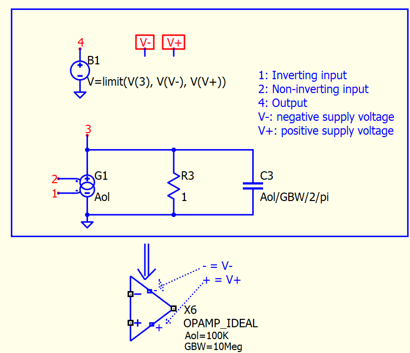
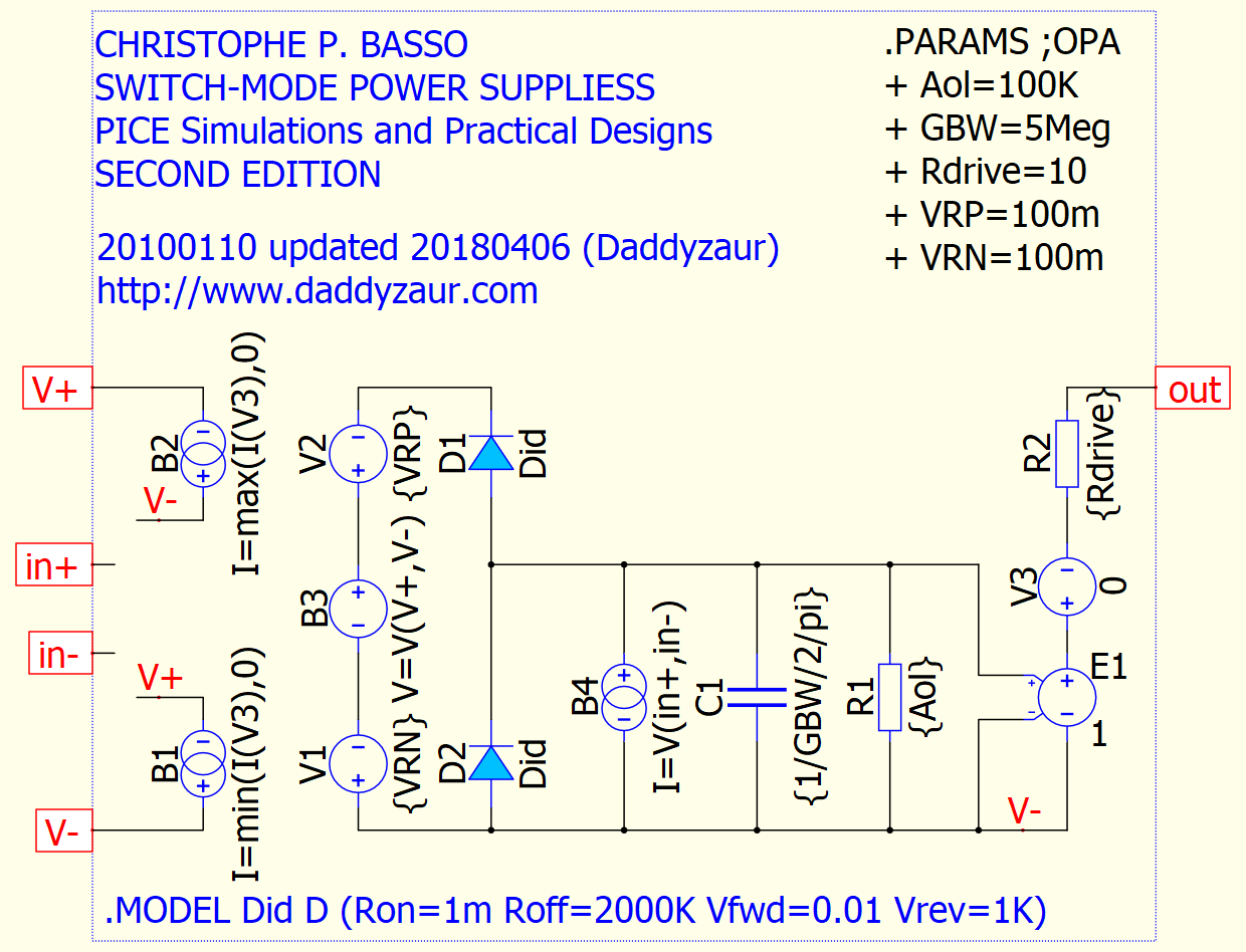
C. Basso implemented a very clever limiting circuit for the output voltage, see Fig. 2.47, page 153, Second Edition. There are some other features he added for the ideal opamp throughout the book, but for the subject at hand that one is your reference. You must be careful now how you define the internal current source, to limit the peak current to reasonable values, even if you must push some coefficients to the capacitor and resistor expression (check my model). Only then the idealized diodes will be able to reasonably clamp the internal voltage levels. And the clamp mechanism must be internal, without any residue on any of the opamp pins (the pole model is internal). To the best of my knowledge, there is no other mechanism I was able to find to limit unreal current and voltages, except for what Basso came out with.
Just a side note, do not assume that a basic model “works”, only because you tested a simplified little circuit with a basic GND connection. A first or a second order model is just a distinction of no importance, if the model shows random currents and voltages: it could have some limited academic value, but for real life products what matters is realistic power rail currents and how the model works on floating applications. You risk to blow up your prototype if you do not really verify the models as close as possible to real life conditions. If you’re more of a software guy, you will always be tempted to ignore and discard real life product conditions. For the hardware side guys, that’s all that matters, we cannot afford to blow up in smoke expensive hardware and work time. Most of the opamp applications are not connected to GND, but floating. Signal conditioning, current sensing on the positive or negative rail, all circuits with ground bouncing (pretty much any application) will require floating opamps models. If you take your time to check the default IP model from QSPICE you will see an extreme error on the power rails currents, and completely random step response on the output, with gigantic and unexplained spikes.
For reference you should check this post: Generic OpAmp problems
I quickly went through the book of C. Basso, and in Fig 2.47, it recommends using diodes as an active clamp for source clamping. Regarding the opamp shown in your simulation file, did you propose it by merging a single pole with this diode clamp idea? It seems that the opamp model in Basso’s book is ideal and does not include a single pole. I just wanted to confirm if my understanding is correct. Or more details about this in other sections of the book?
OR, essentially, the opamp model you proposed is your own creation?
@KSKelvin, you again shift the conversation to something of no importance. One, two, or countless internal poles inside the model is of no consequence for the subject matter of this thread. Feel free to decorate the model with as many poles inside, as your heart desires. The problem is how to make the model work on floating nodes (the ideal model from QSPICE does not), and how to most accurately reproduce the power rail currents (the ideal QSPICE model does not). Basso shows us how to do it, I learned from him. Yes, I added a few things around for power rail currents. Details about poles insides can be added as you wish, providing that you do not mess-up the most important requirements for an ideal opamp that must be used for real production work.
I am simply seeking additional reference information to better comprehend the model. If this is your idea, I understand that I need to thoroughly examine the circuit details. However, if there is a specific reference book/article available, I would prefer to read it first. I’ve mentioned before that I am not an expert in opamp modeling, so just few more questions in confirming what am I looking for. Maybe it would be best for me to end the discussion here, as I realize I am not well-suited for discussing opamps and should focus on my primary area of expertise.
@KSKelvin thanks, you engagement helps keeping this subject in focus to clarify important issues. I think you’re one of the main moving forces in this forum, and I can bet the guys behind QSPICE will pay attention when you get involved. Appreciate it.
There are plenty of references, articles, examples, and explanations about the opamps, not interested to discuss all of them in this thread. I wanted to isolate only the two main issues with the analog IP models from QSPICE. Some people could use them and end up with problems they cannot explain.
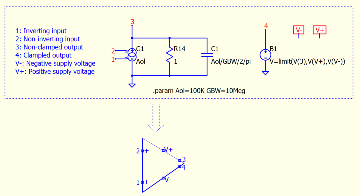
@KSKelvin what do you think about this implementation of op-amp with saturated/clamped output voltage? Could you implement such a symbol to have also this symbol in library?
I assume in this discussion, it is not intended to model supply current but only output clamp.
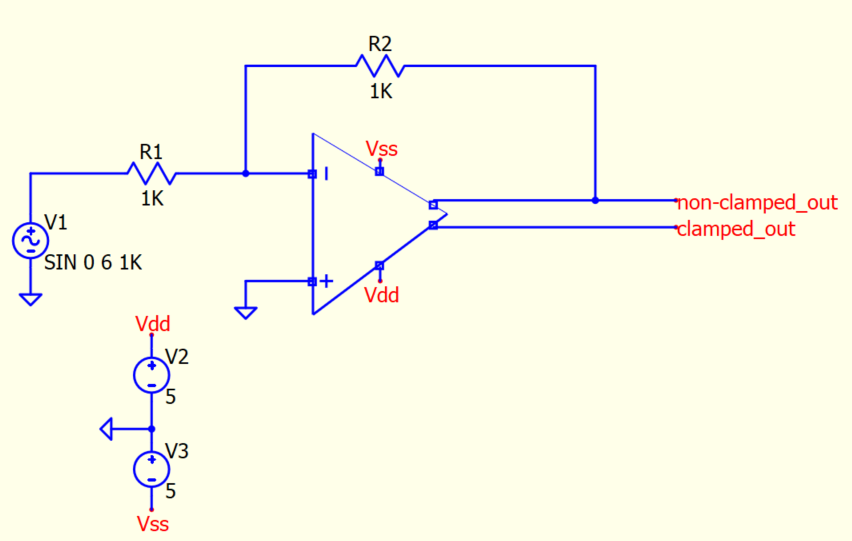
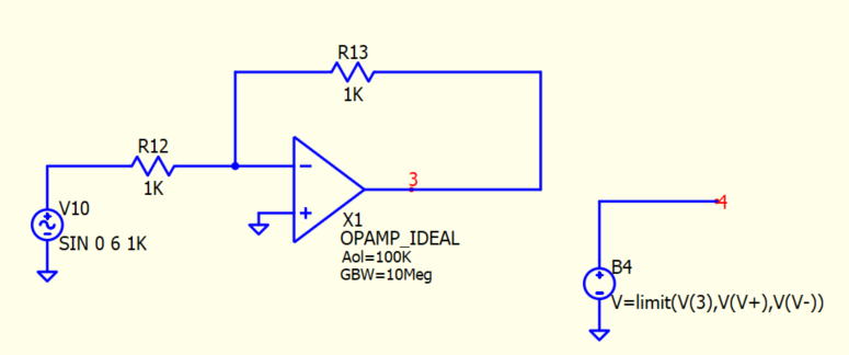
The problem of using B-source limit is that, this is not actually an opamp structure, this is an opamp + limiter. For example, if you connect R2 to clamped_out instead of non-clamped_out, this structure won’t work. Therefore, you are using two circuit devices to achieve a clamped waveform. We sometime use this technique in simulation, I think it is not necessary to build an integrated symbol as people will confuse about that.
I already have a SinglePole opamp model with supply input in my symbol library, which follow an active diode clamp circuit by Basso. However, I never focus on modeling supply current as this normally not my concern in my simulation.
But you can always build your own library (as it seems you already made a symbol for this one). If you have long term plan in building more symbols, consider to use Github, upload your work and share with community.