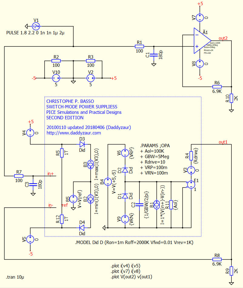
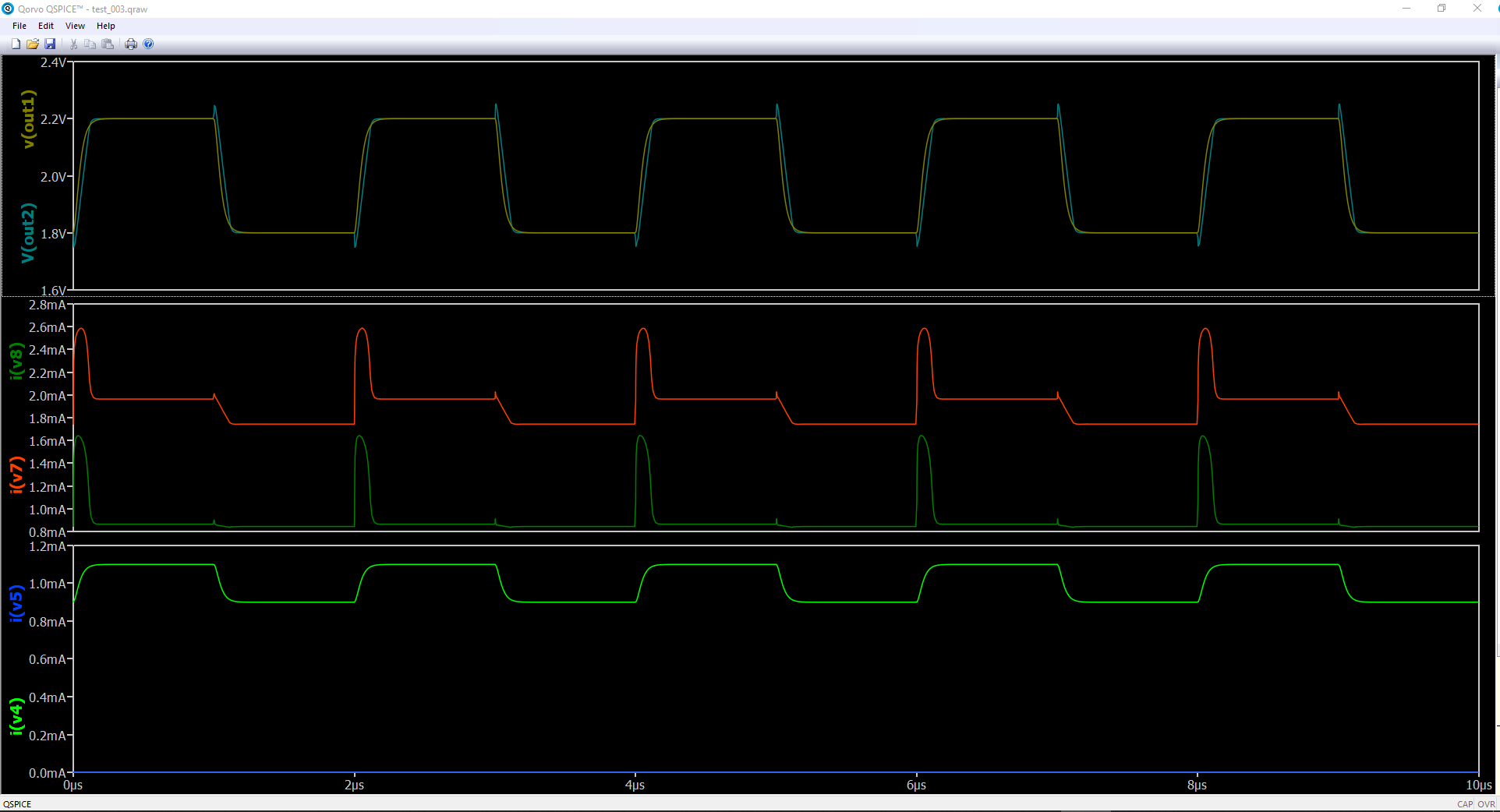
Probably I am missing something with the generic OpAmp. I suspected the old issue with net names messed up in the sub circuits, but this one seems to be altogether another problem. Hopefully somebody else could help here. As shown in this example, the generic OpAmp has very unnatural output waveforms, with weird spikes. Also, the power supply rails are showing some kind of random currents. That in itself is an issue with OpAmps where the input/outputs and the local power supplies are floating and the power is generated with local and linear LDOs. An example is here, showing the outputs and the power rail currents, side by side, from a “normal” OpAMP and from the default, Generic OpAmp.
test_003.qsch (29.0 KB)
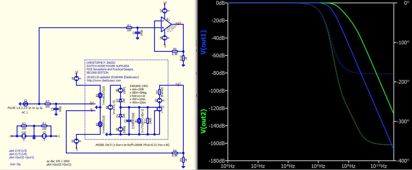
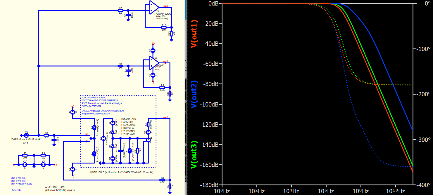
I am not entirely certain if I am correct, but in discussion about the RROPAMP in below thread, my observation is that the model of the RROPAMP consists of two poles (pole1,pole2) and a zero (zero1). This zero is a right-half plane (RHP) zero, and based on the profile of V(out2), the spike appears to be the effect of RHP zero (i.e inverse response).
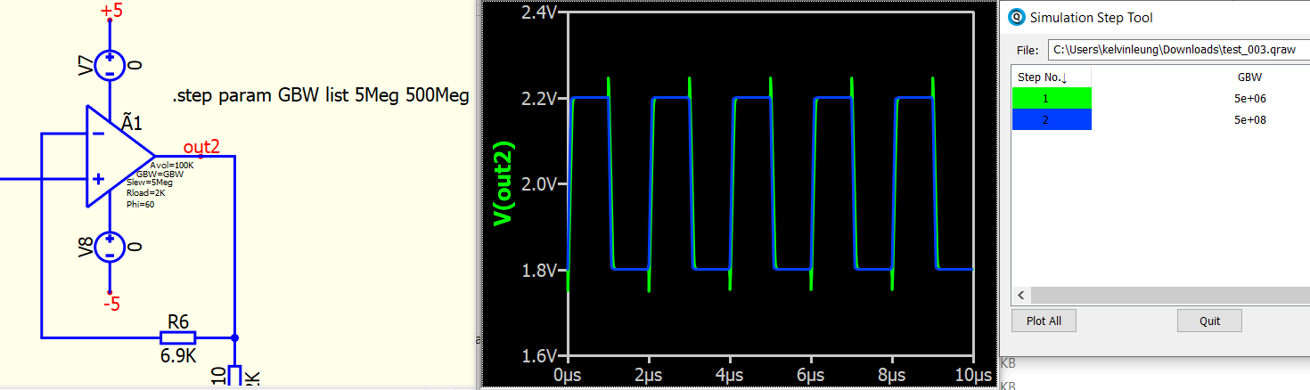
If you increase the GBW (gain-bandwidth product) to a very large value, such as 500 MHz, it can effectively move that pair of zero and pole (zero1 and pole2) an orders away from your signal frequency. As a result, the weird spike disappears.
Rail-to-Rail Output OpAmp (Ã-Device RROPAMP) Instance Param - QSPICE - Qorvo Tech Forum
By compare bode plot, your “normal” opamp model is a single pole (phase to -180), and Qspice RROPAMP has an additional pole zero pair (phase to -360).
Here is a comparison by adding an ideal single pole opamp.
Attach the simulation file for your reference.
test_003_plusIdealSinglePole.qsch (29.7 KB)
I do not fully agree we should assume this part would work best/better under some very abnormal conditions. Let’s start from DC, low frequencies, higher frequencies, and then move up to extraordinarily high frequencies. It took me a while to find these issues, because I did not suspect things are that bad. Let’s look at the power supplies currents for example, and move along from there. An OpAmp is not supposed to be used for AC analysis only.
@KSKelvin, when you’re talking about some double pole at about xxx MHZ, are you taking into account the gain at that point? Can you get that gigantic voltage spike when the gain is under -80 dB? Or have you ever seen a real OpAmp on bench to exhibit such behavior? What about the current into the power pins, have you check that one and compared to the output current?