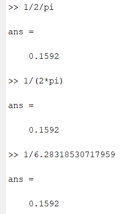
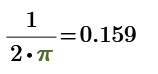
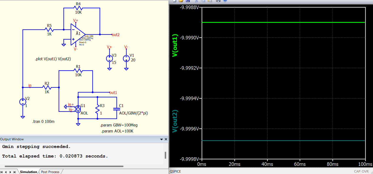
C3 should be Aol/GBW/2/pi or Aol/GBW/(2pi)? Compared with what is written in subckt opamp from ltspice in C3, then the second variant seems to be the good one (with (2pi = 6.283…)), right?
I looked in your library and saw that the opamp is implemented with 2/pi.
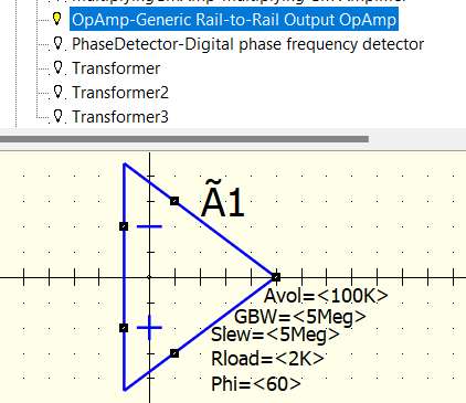
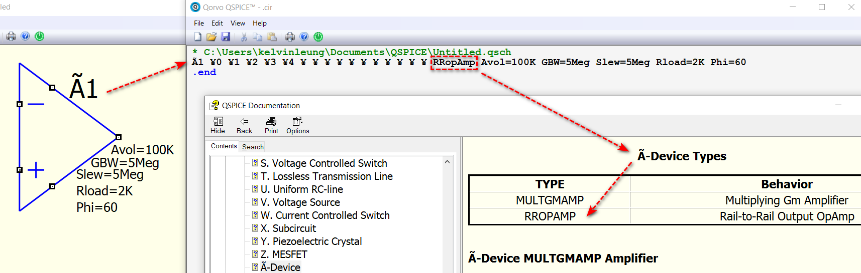
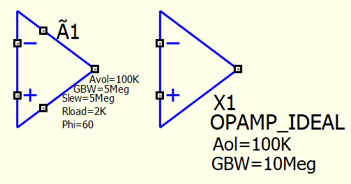
Qspice Symbol & IP Browser Opamp-Generic Rail-to-Rail Output OpAmp symbol is Ã-Device (unique for Qspice). Ã-Device has two types : MULTGMAMP and RROPAMP, and this one is RROPAMP. Detail can refer to Qspice HELP Ã-Device section.
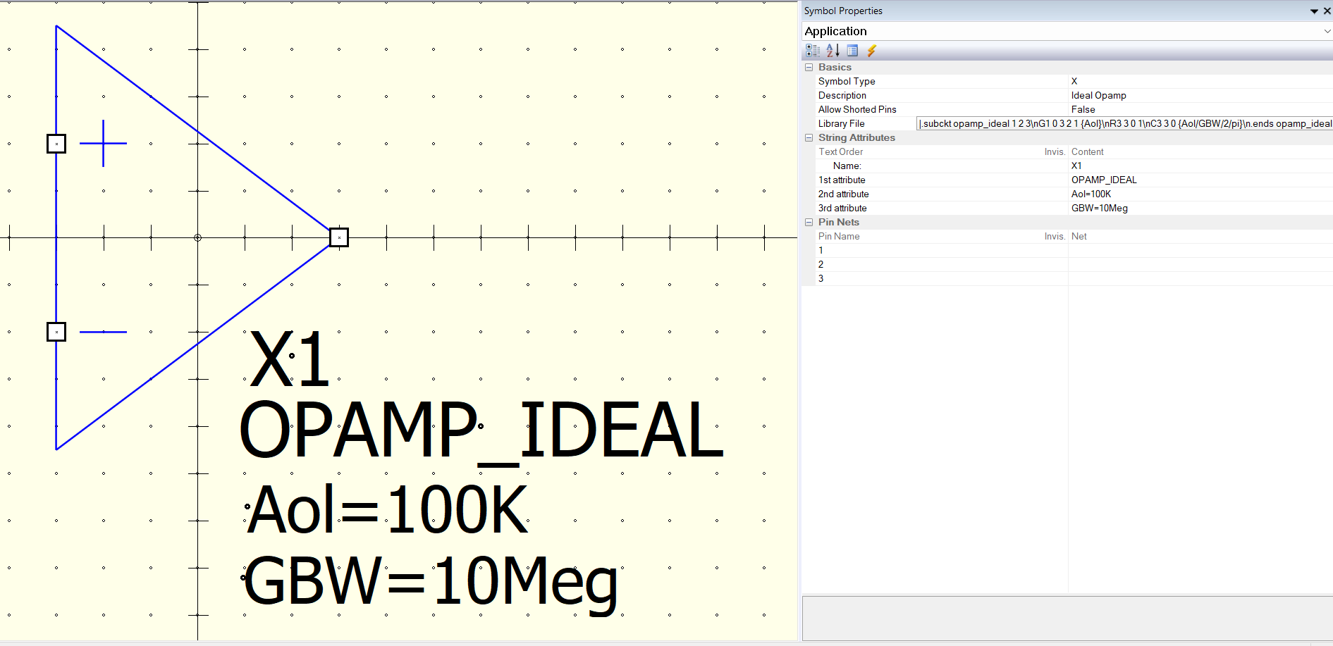
As I worked with LTspice for very long time. For compatibility, I created an opamp model which is based on opamp.sub in LTspice library, and also documented the ideal behind this model structure.
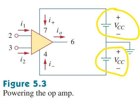
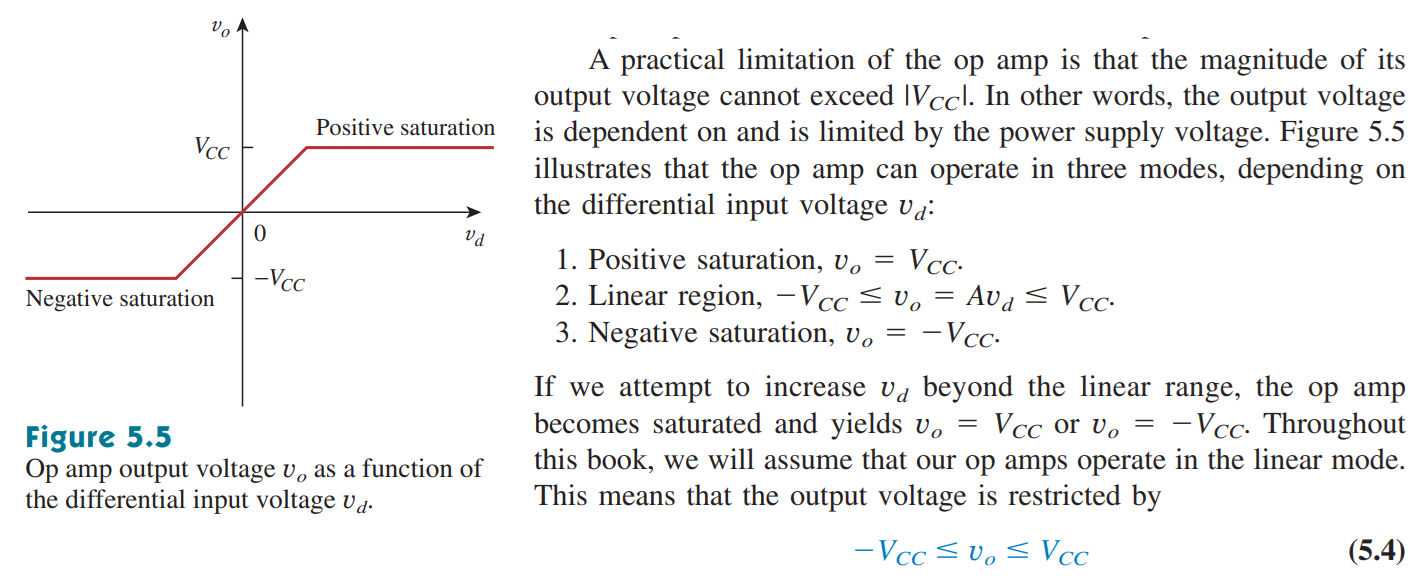
Yes, but your opamp model does not take into account the rail influence. If voltage at non-inverting input of opamp > positive supply voltage, then the output needs to be limited at the positive supply voltage. The same for inverting input of opamp vs negative supply voltage applied to opamp. That’s why I loooke at opamp given in the qspice library
@marcos.uniovi how did You used this component in your simulation as opamp? Did work good this component? Or you did not verified this opamp to see If it is working as expected or not?
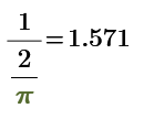
1/2/pi should be equal to (1/2)/pi or 1/(2/pi), just depend the definition is left associative or right associative. I totally agree with extra parenthesis, as can prevent confusion for anyone to read the code.
To be honest, writing 1/(2*pi) with 1/2/pi was not my practice when I was in university. As I saw a senior engineer used syntax likes Xc=1/2/pi/f/C in my career, and as a copy cat I started this style.
The calculator I bought in high school is left associative, and that why this never confuse me.
@Cornel In simulation, we try to bring a real world device into simulation and to study its response. This process is called modeling.
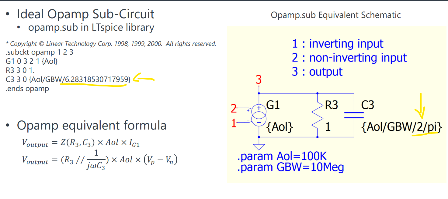
The opamp.sub in LTspice, is target to model the most fundamental concept of operational amplifier.
Fundamental formula of opamp is Vout = AOL * (Vplus - Vminus), with AOL → infinite Operational amplifier - Wikipedia
If you look into opamp.sub, by removing C3, it is exactly this formula. The beaty of this behavioral model is how smart it is by setting R3 to 1 and with a C3 to add a pole in transfer function to simulate a frequency response from a first-order system.
This is a textbook model and of course not that practice. But don’t underestimate this model as it is great for proving a concept as the simplicity it can offer.
What I normally do is that, in symbol creation, I create a symbol in same size, such that I can change to a more complex model easily in a schematic level. You always want to start your simulation with simple device, ensure it works and move to higher complexity.
Sometime, you just found no extra insight from a more complex model as compare to an ideal one but which caused you many more seconds of simulation time.
I haven’t study Ã-Device (TYPE : RROPAMP) but have a section talking about Ã-Device (TYPE : MULTGMAMP) in my github device guideline. In the description of Ã-Device RROPAMP Amplifier, it describes RROPAMP is implemented with two Gm amps (Gm amps : MULTGMAMP). May be studying MULTGMAMP first will eventually help you to fully understand RROPAMP. Type MULTGMAMP also offers voltage limit.
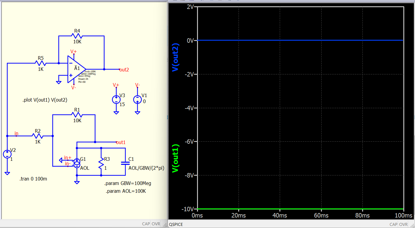
Your post title is “Good or bad Generic Rail-to-Rail Output OpAmp”… and your first post with V(out2) at 0V… well, are you asking question why that Qspice model give you 0V output instead of -10V output likes opamp.sub ideal model can do?
If this is your question, it is because you set V1 to 0V and therefore, negative rail V- is at 0V.
As later you mentioned need rail limit… so, I am not quite sure your intention was to set V1 to 0V to show me the limitation of using opamp.sub or you have difficulty in that Rail-to-Rail output as you forgot to set V1.
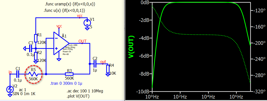
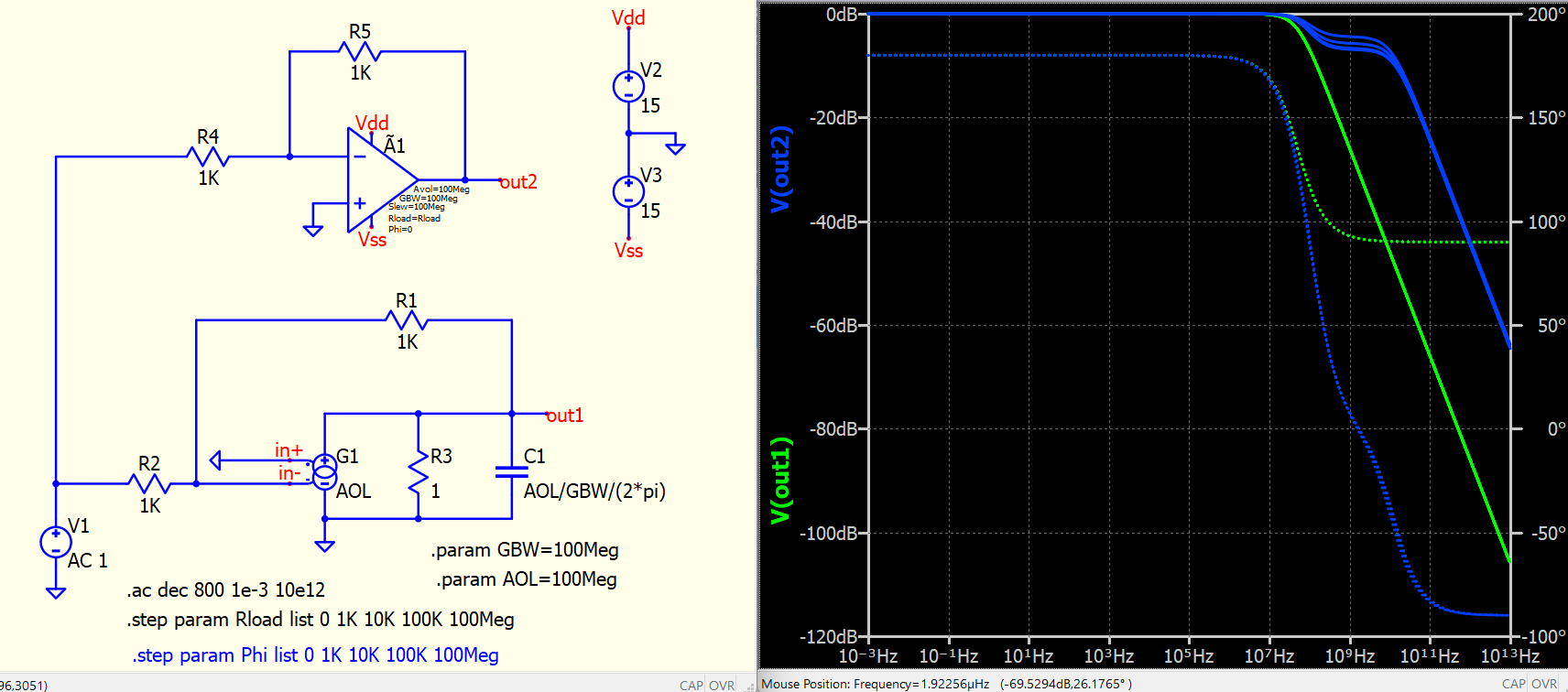
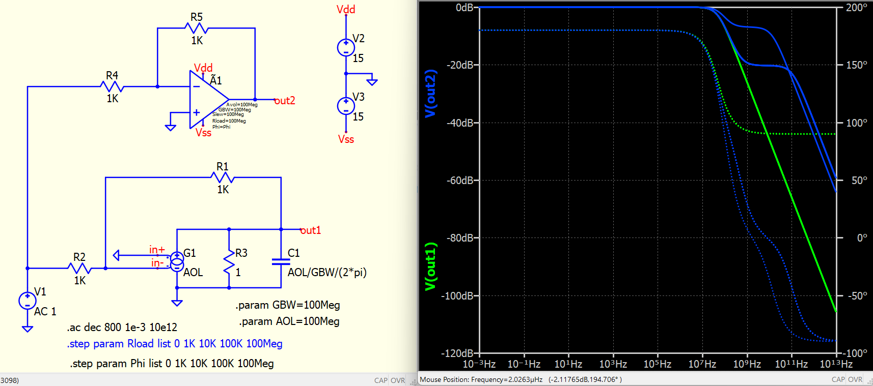
Now the thing is to how Rload and Phi are influencing the response.
Kelvin, of course your model of opamp is ok, and I like it due to the simplicity and its easy to understand it. What was/is missing and I wanted to see in the model is supply voltage of opamp and its influence on the behavior of the output (that’s why I used the opamp from qspice, but this opamp inside the qspice library has some parameters like Rload and Phi that I do not fully understand at this moment):
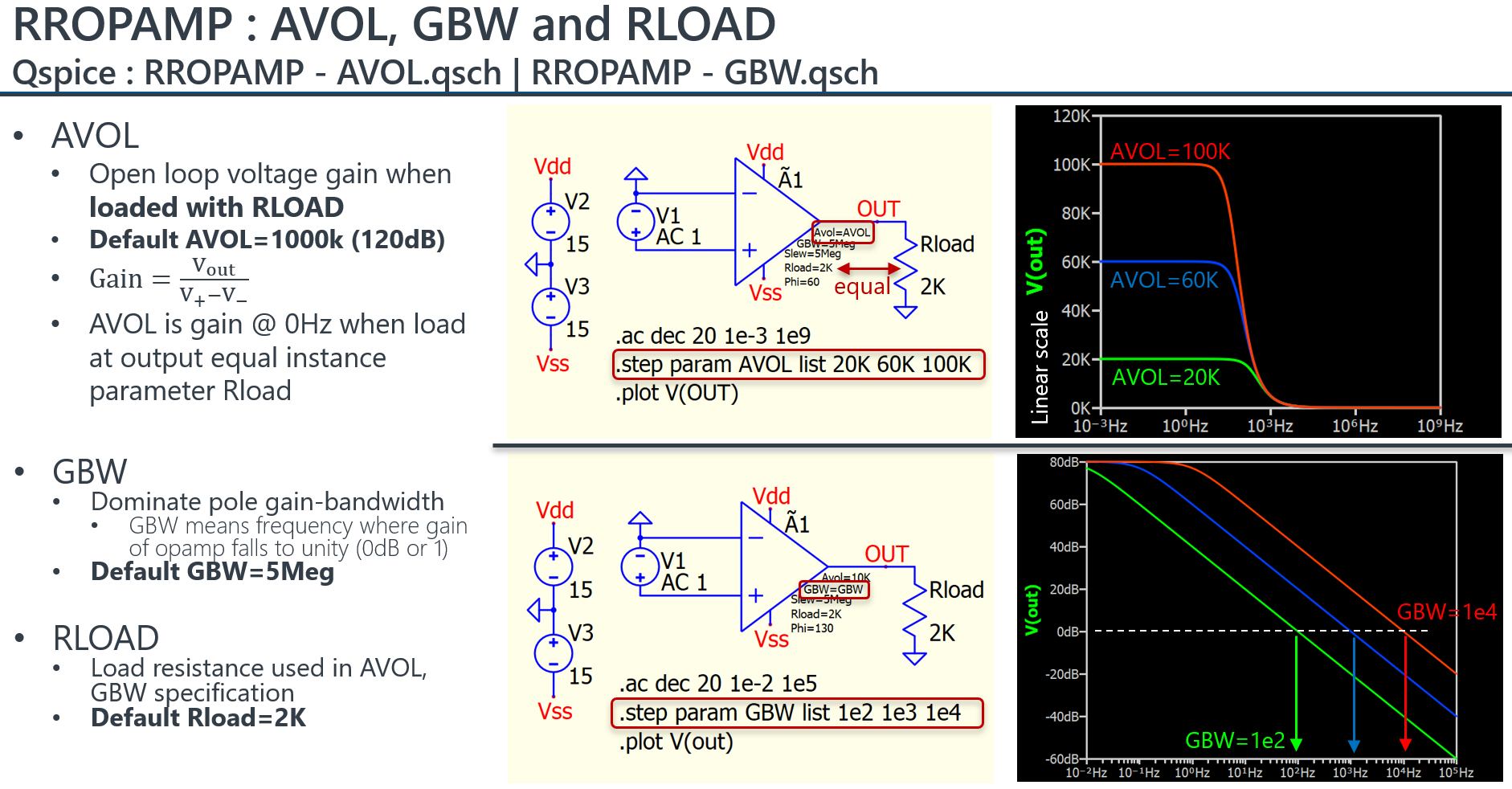
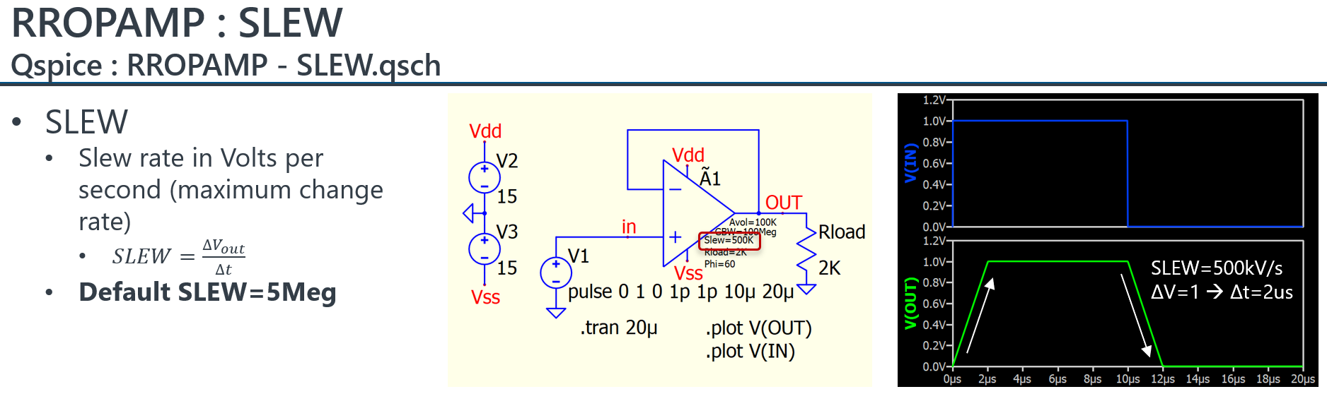
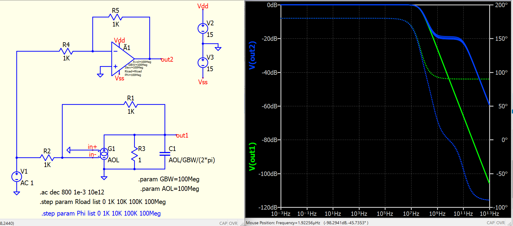
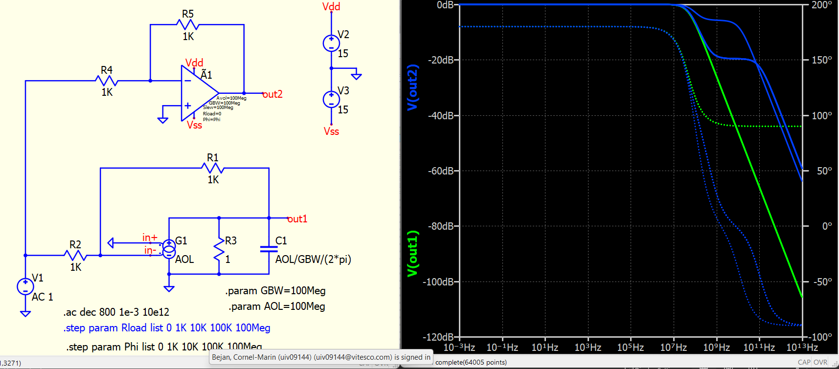
I ran a series of tests for instance parameters (AVOL, GBW, PHI, RLOAD and SLEW) of Ã-Device, type RROPAMP (behavior model of Rail-to-Rail Output OpAmp)
Other instance parameters are possibly similar to definition of MULTGMAMP and can refer to my device guideline.
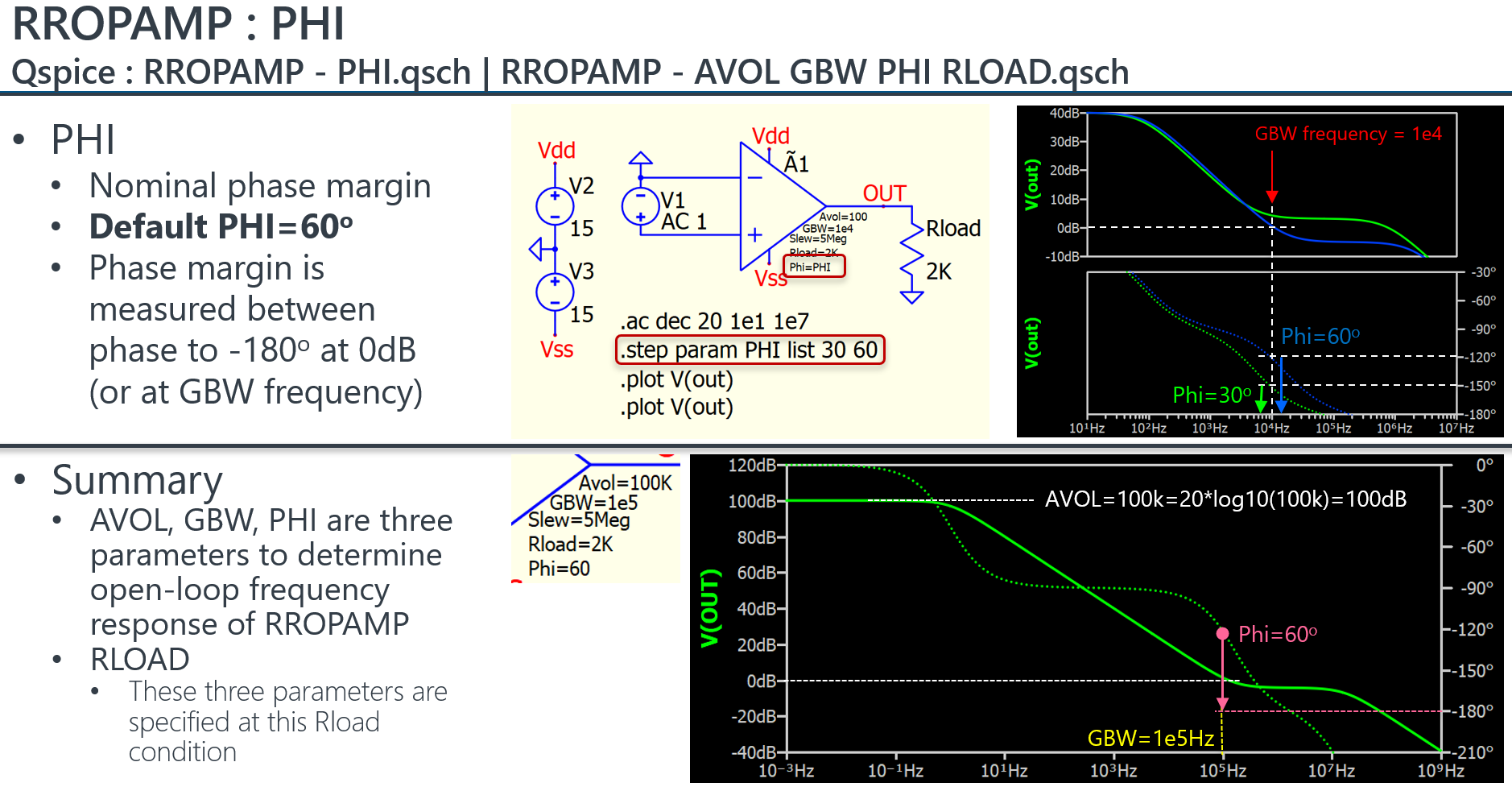
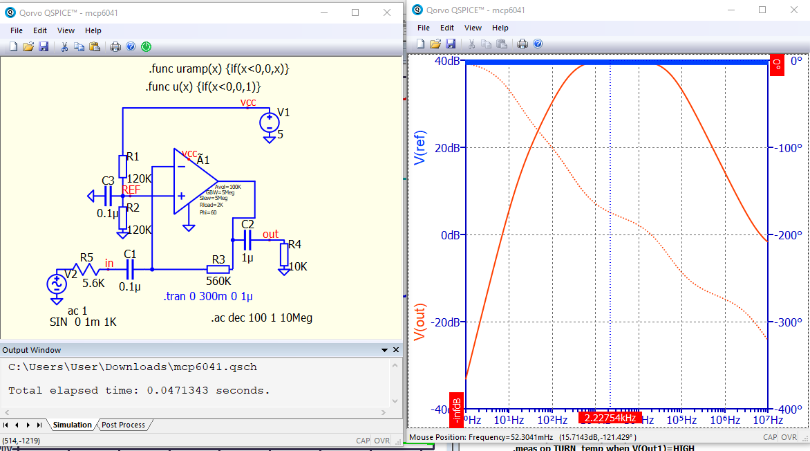
In short, AVOL, GBW, PHI and RLOAD are together to define open-loop frequency response of this Rail-to-Rail opamp. I found this very interesting as it offers an easy way to model an opamp. Based on frequency response, characteristic is defined at an external resistor equal Rload condition, with 1st pole by AVOL and GBW, and 2nd pole and a zero by PHI. In frequency response curve, it quite clear that two poles and a zero are used to control frequency response to meet the defined parameters.
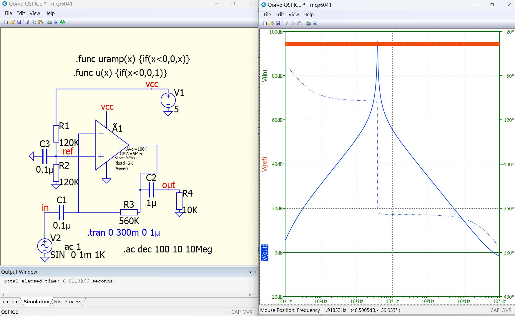
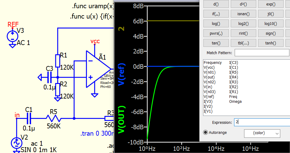
The resistor has nothing to do with it. I figured it out. I’m confused by the meaning of REF.
The problem arose due to the fact that everything is supplied in dB. With a linear Y scale, voltage REF=0. And in dB it is equal to -infinity. How to show such a value? I would prefer the REF line to be at the bottom rather than at the top.