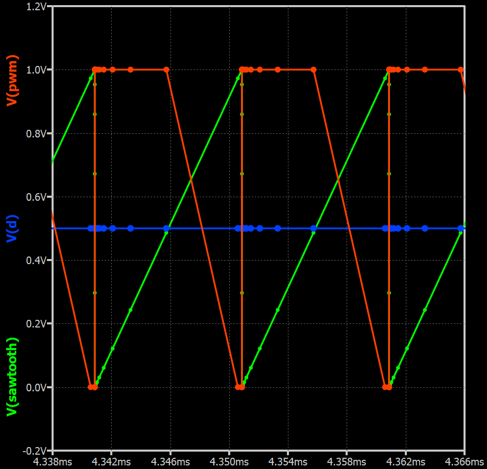
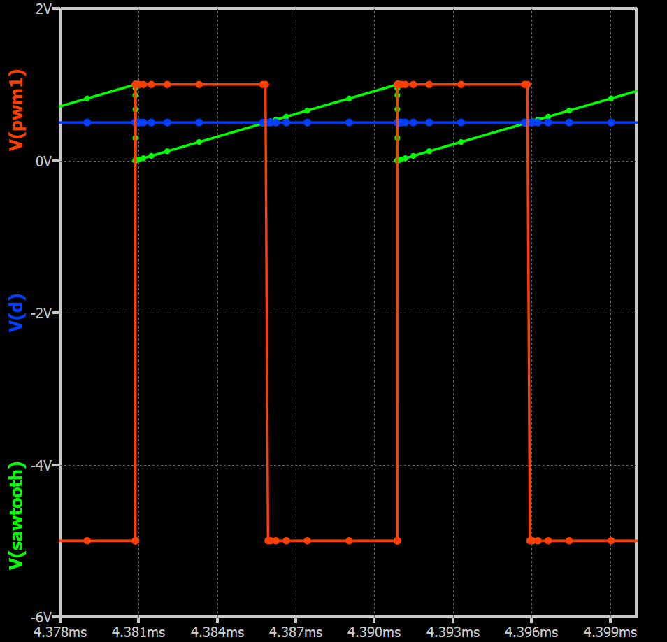
I would have expected that even if Stop Time = 10ms while Maximum Time Step = 10ns, then the graph/calculation would show the points corresponding to Maximum Time Step, and not the points corresponding to Stop Time…
What îs wrong?
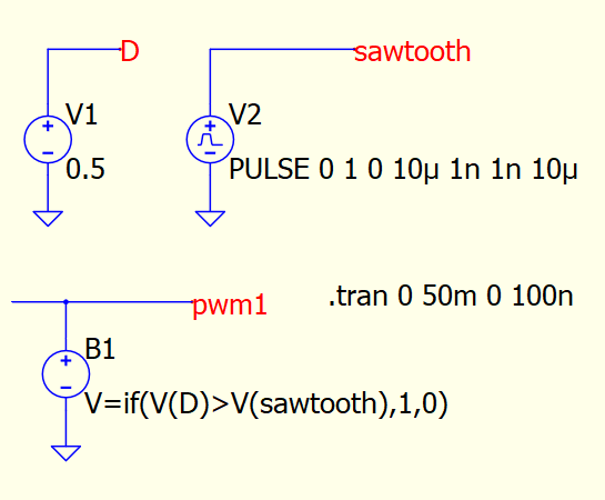
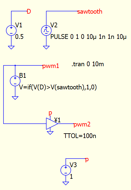
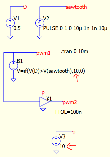
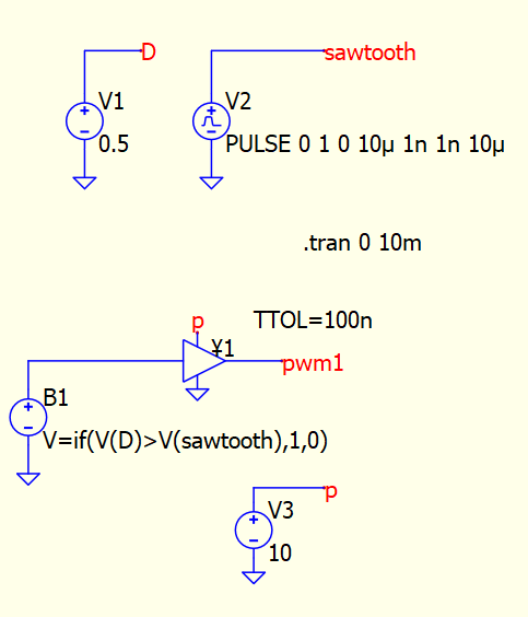
What is wrong is that B-sources do not implement temporal tolerance (TTOL), because it was not anticipated they would be used for this purpose. KSKelvin, in a recent thread has suggested some workarounds that do not involve stop time or maximum timestep.
I am wondering if it will not be possible to implement in B source this temporal tolerance (of course, this is a question for @Engelhardt)… because many use in B source logic. It will be helpful if this is considered to be added.
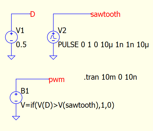
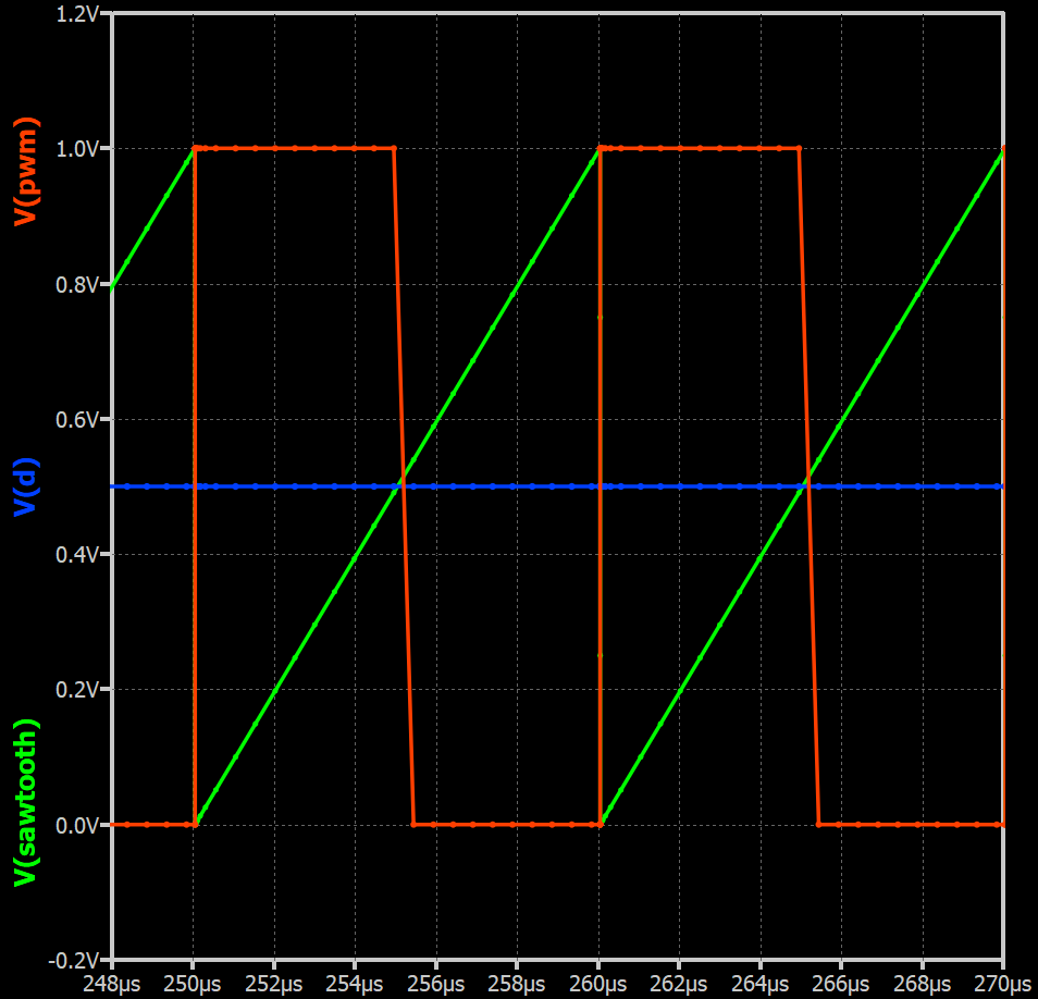
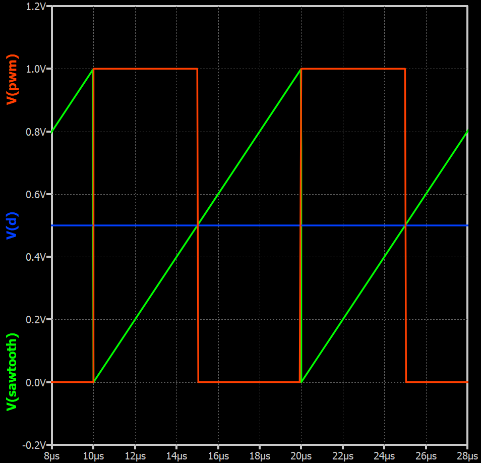
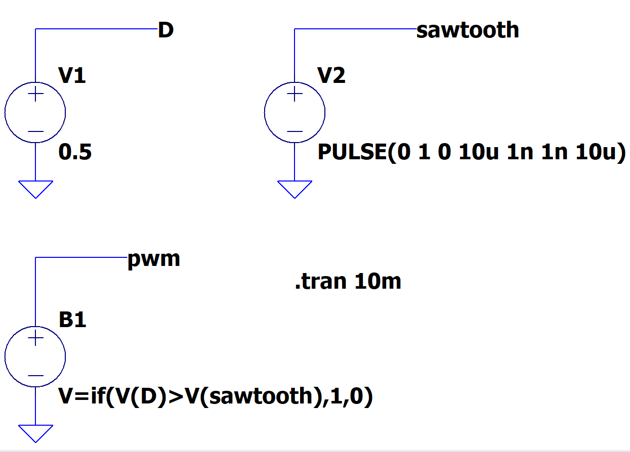
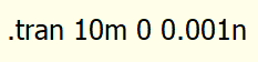
Your .tran syntax in Qspice is incorrect and that why maxstep is not in effect.
If you compare your LTspice and Qspice .tran, you will find that different.
I answered this similar question before and you can refer to this post.
Refer to two of my reply in this link
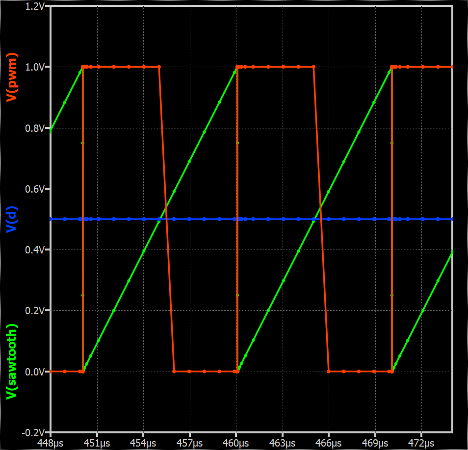
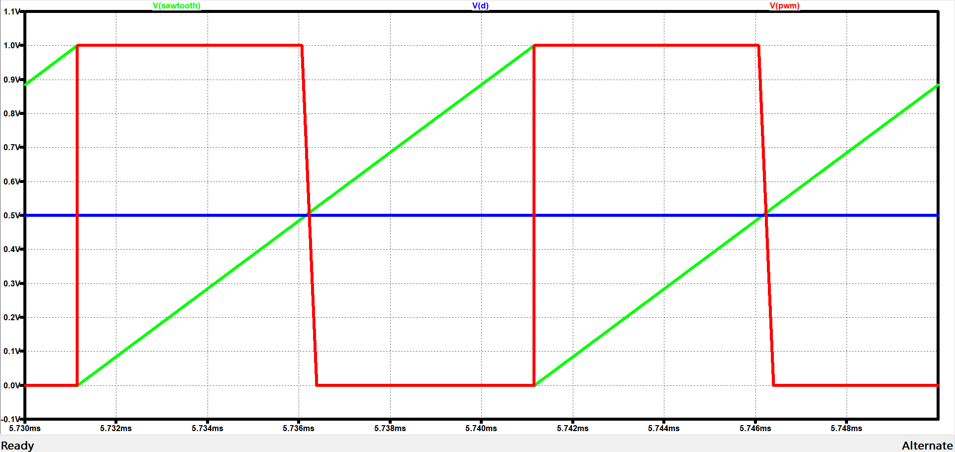
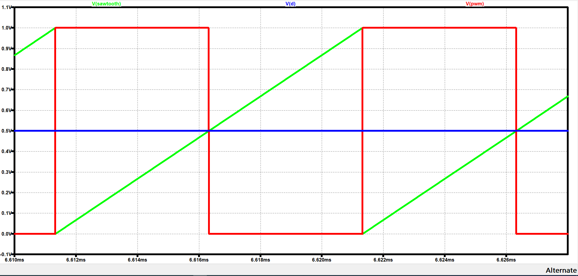
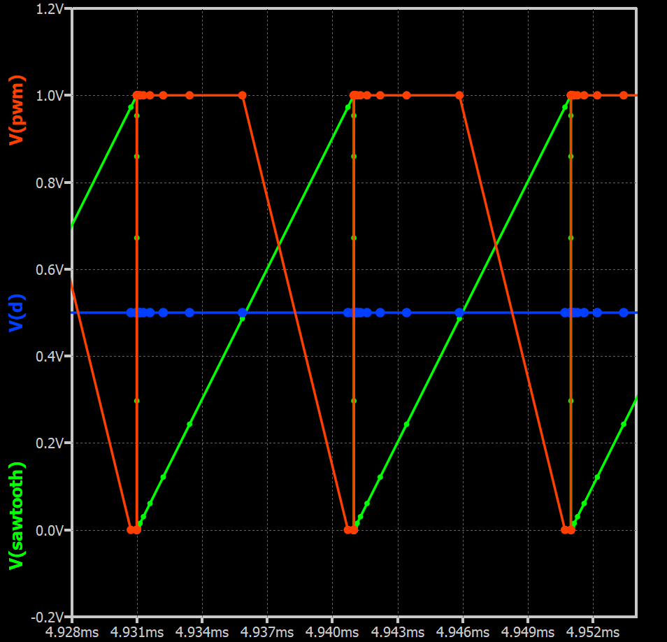
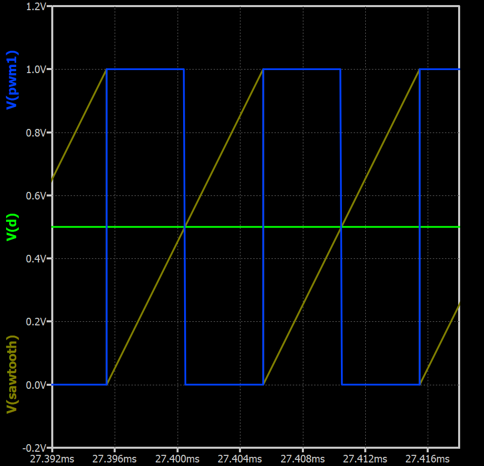
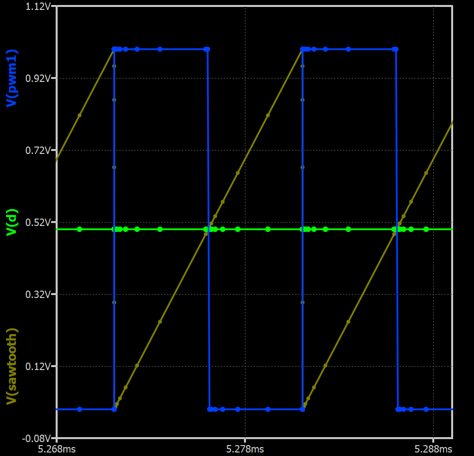
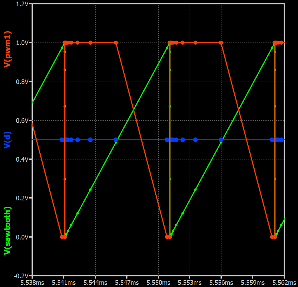
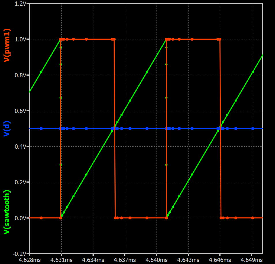
My understanding of TTOL is a temporary timestep control during simulation. Qspice calcuation is correct in every @Cornel example, but visually we just don’t like the look of the waveform as no extra points to make a vertical line in plot. Therefore, in this particular case, this is more like a “Visual Problem”.
With that, I don’t think it is B-source problem. B-source handle all kind of mathematic formula, and the challenge is only when we operate a B-source in a “logic” condition (e.g. using if function)
Learning when and how to use TTOL is an important key in Qspice. This parameter is not in LTspice, once you understand that, you will find Qspice can run a switching circuit much faster and TTOL in many ways play an important role to that.
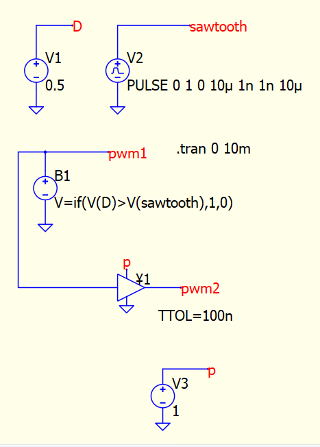
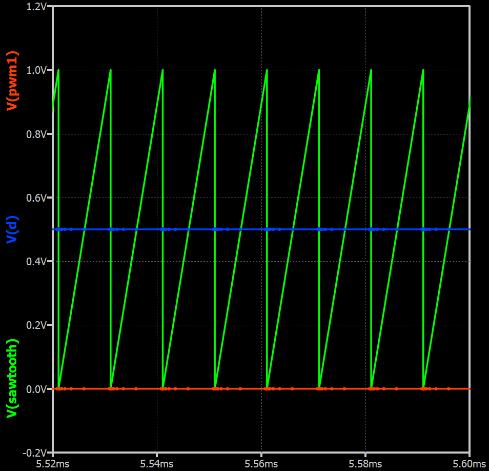
When limiting the MAXSTEP in .tran syntax results in a slower(or more) simulation time required for the simulation than the variant using a TTOL device (a buffer). See total elapsed time.
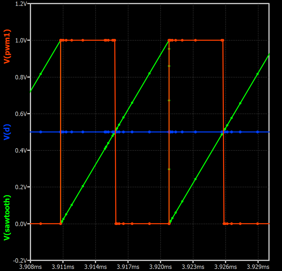
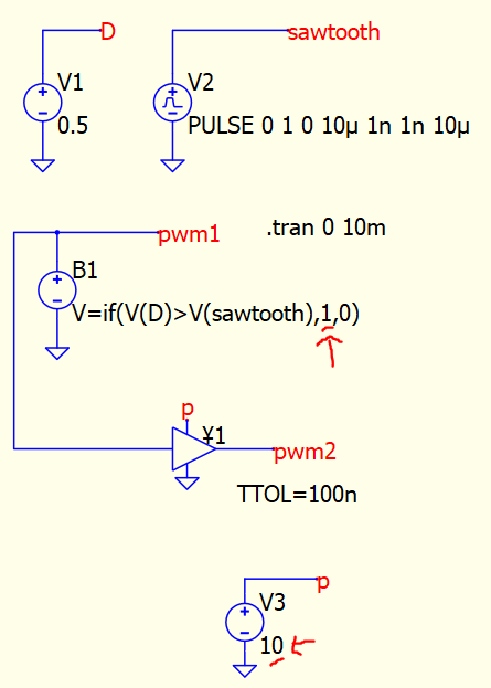
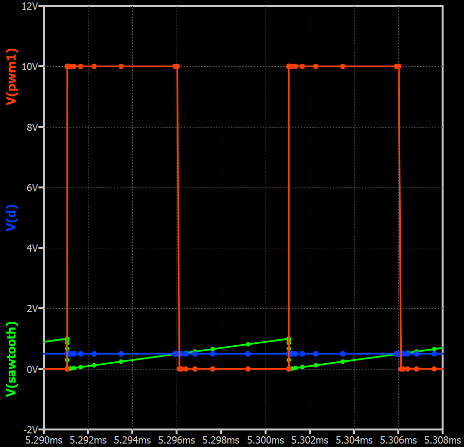
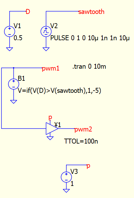
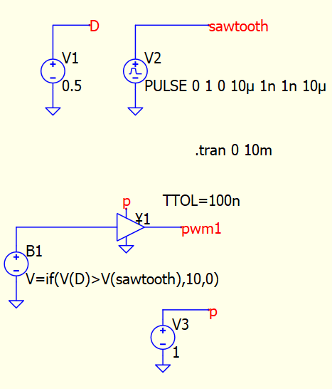
It seems that the supply voltage of the TTOL device must be lower than the comparison value in if statement to properly work. But as you can see the amplitude of V(pwm1) does not change if you put in if statement any value greater than the supply voltage of TTOL device.
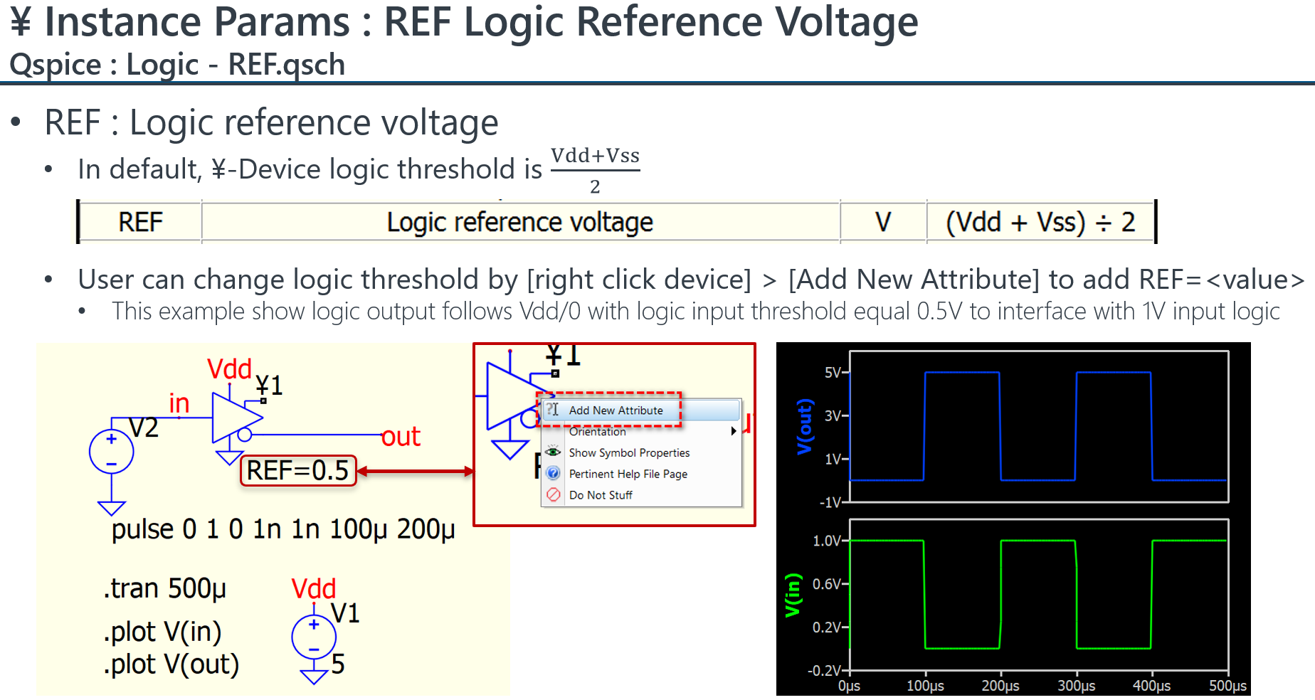
If you refer to help, ¥-device has an instance parameter REF. This is logic reference voltage to determine input threshold of HIGH and LOW of logic. In default, REF=(Vdd+Vss)/2.