Hello QSPICE community.
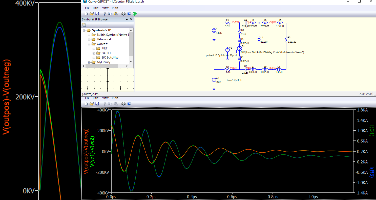
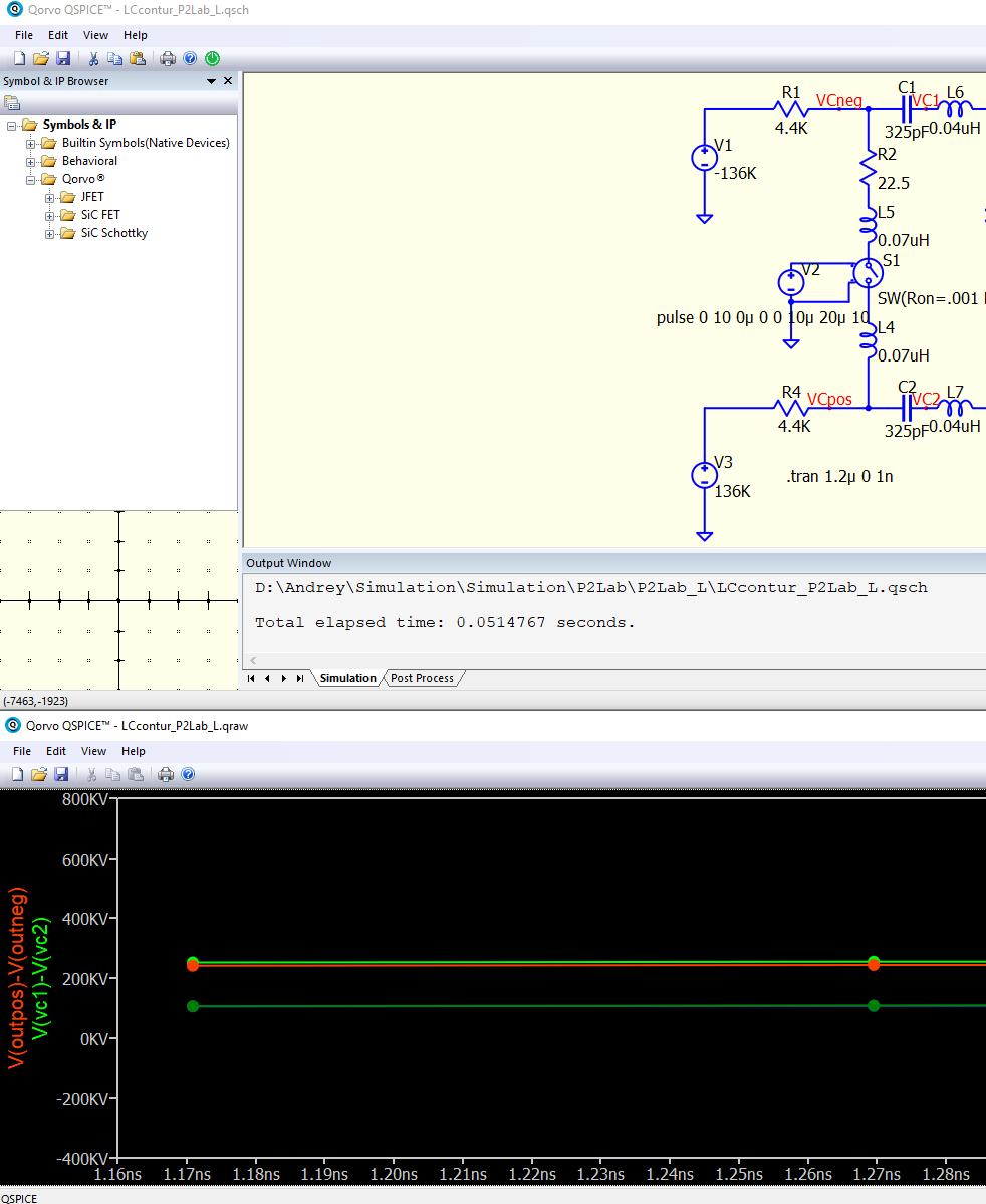
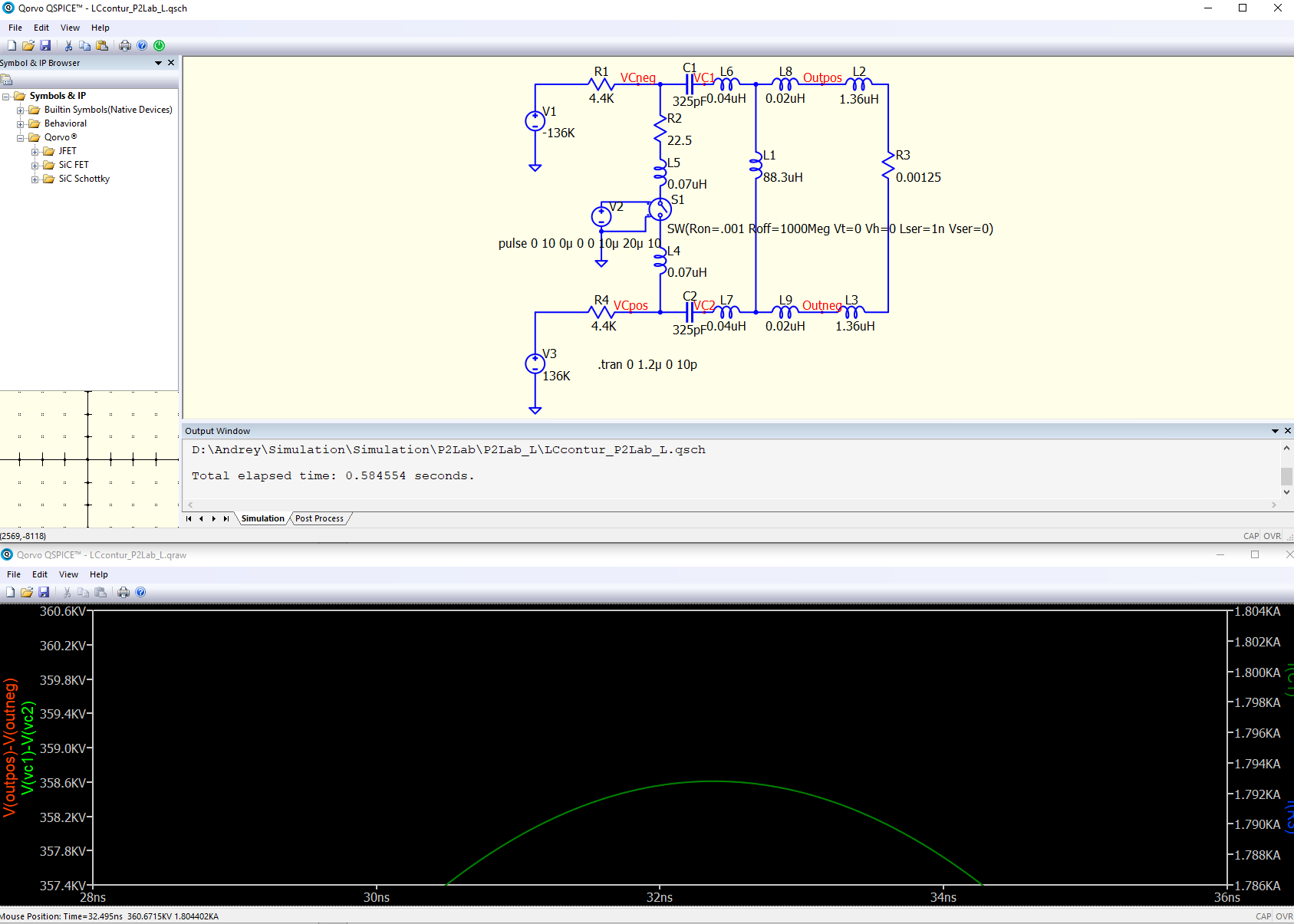
This is the shematic:
The simulation results:
The signals (before updating the Spices) is shown on the left.
At the initial moment of time there were several points with zeros.
After the update, there are no zero points.
Also, after the update, the amplitude of the signals decreased slightly.
Before the update, the results were almost the same as Altium Designer.
After the update QSpice, the amplitude of the signals is less than the results of modeling the same circuit in Altium Designer.
Thanks for any help.
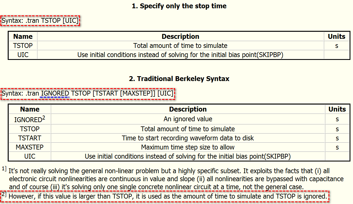
from your screenshot, .tran 1.2u 0 1n
If you refer to help, you are using Berkeley Syntax,
where .tran IGNORED TSTOP [TSTART [MAXSTEP]] [UIC]
1.2u = IGNORED
0 = TSTOP : in Qspice, if IGNORED value > TSTOP, TSTOP set to IGNORED value
1n = TSTART
So, your simulation is from 1ns to 1.2u
The correct syntax should be
.tran 0 1.2u 0 1n
Did you use this same .tran directive in your simulation before updated Qspice?
I used the .tran directive before update.
Before updating ( if .tran 1.2µ 0 1n), the signal has been displayed from the zero second.
After updating ( if .tran 1.2µ 0 1n), the signal is displayed from the first nanosecond.
After updating (if .tran 0 1.2µ 0 1n), the signal is displayed from the zero second. This is right.
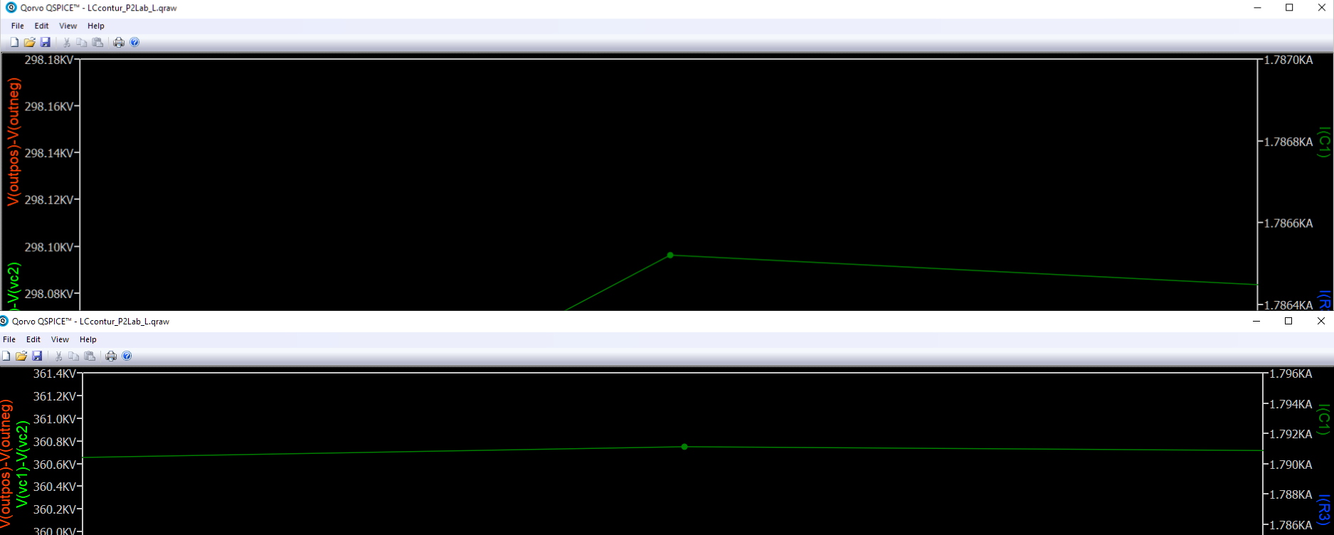
Why do the directives (.tran 0 1.2u 0 1n) and (.trun 1.2u) give different amplitude of signals?
At the top - .trun 1.2u
at the bottom - .trun 0 1.2u 0 1n
The directive (.tran 0 1.2µ 0 1n) models more accurately.
Thank you.
You didn’t update Qspice for long time? There was an update if value in IGNORED > TSTOP months ago, may be that causing the different.
If you go to HELP > Simulator > Command Reference > Non-Linear Transient Analys(.tran), Qspice offers two .tran syntax, in which syntax depends if you have a 2nd numerical input.
Therefore
.tran 1.2u means transient simulation to stop at 1.2us, but no maximum timestep specified.tran 0 1.2u 0 1n is Berkeley Syntax, time to start recording waveform is 0s and stop at 1.2us, with maximum timestep 1ns
Qspice is adaptive step size algorithms. If you define a maximum timestep, each simulation step is force within MAXSTEP value. Therefore, if you set MAXSTEP to 1ns in this simulation, it run simulation more precisely. Downside is that it increases simulation time. If you find no MAXSTEP result is good enough, you don’t have to include MAXSTEP in your simulation.
Another method to specify MAXSTEP without using Berkeley Syntax is
.tran 1.2u
.options MAXSTEP=1n
Advantage of this syntax is that, you can comment .options to quickly switch between MAXSTEP and no MAXSTEP in your work. You can press “;” to comment a directive, or right click on text to select comment it.
OK
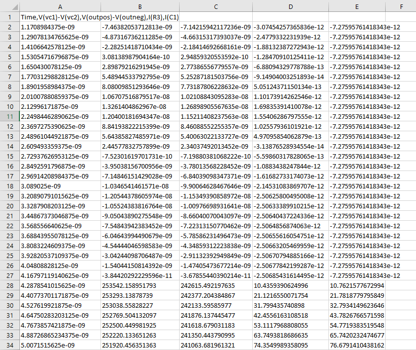
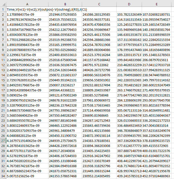
Before updating ( .tran 1.2µ 0 1n) - the signal was displayed from the first nanosecond, but the signals had almost zero values.
The signals has been uploaded to Excel.
The first 4 nanoseconds there were almost zero values:
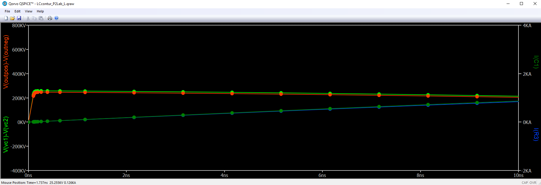
After updating ( .tran 1.2µ 0 1n) - the signal is displayed from the first nanosecond. There are no zero values:
Excel:
After updating If ( .tran 0 1.2µ 0 1n):
Simulation from the zero second as it should be:
Anyway, I got exactly what I needed:
( .tran 0 1.2µ 0 10p) - the results will be more precisely.
Indeed, the MAXSTEP parameter determines the accuracy of the simulation.
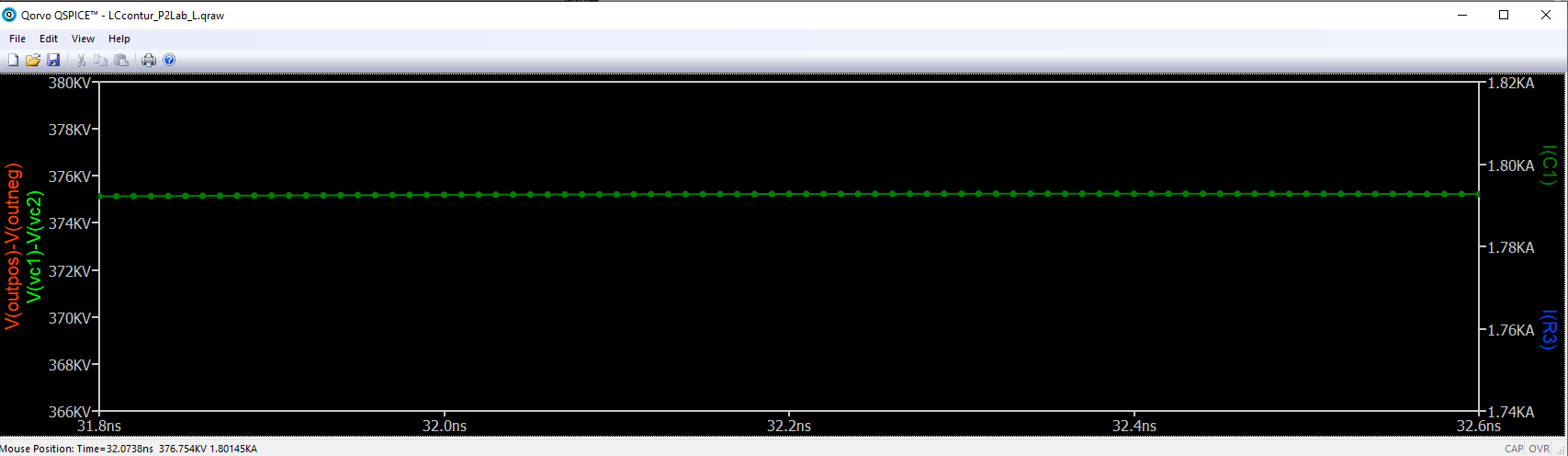
If MAXSTEP is 10p, the simulation results will be as follows
There are many simulation points on the screen:
Thank you.
1 Like