TTOL device to Interface analog and digital

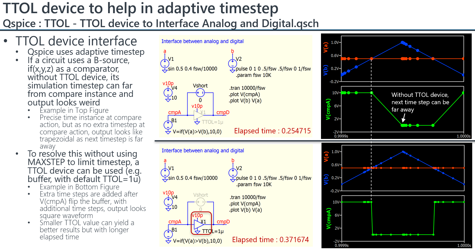
Many of you may already realized this, but I just got myself clear until recent study and take a chance to share that. Qspice uses adaptive step size algorithms, and for example to use if(x,y,z) as a comparator implementation, you may find its output looks trapezoidal instead of square in a long run. Normally, I add .option MAXSTEP to limit maximum time step in simulation, but also significantly increase simulation time.

I just realized that, to utilize a device with TTOL (i.e. Switch, ¥-Device) can help. As TTOL allows one to determine how accurately the switch time should be found, if the comparator output flip event trigger switch action for a device with TTOL feature, extra time step can be added after switch action to achieve an instance response waveform.

Here is an example to compare with and without a buffer after B-source with if(x,y,z) as a comparator.
I just remind myself in many simulators, analog and digital requires an interface device, just like this simulation case. The only difference is that, originally, I didn’t consider this as a digital circuit as if(x,y,z) is not necessary be a 0/1 output but can be a formula or other stuff.

So, I am not sure if any other better method, but at least this can help to balance time step and simulation time.

10 Likes

That is very handy to know - thanks for sharing!
I wonder if we can add TTOL to a DLL block in order to force similar behavior?

Hi, Emrys.

Unless my tests have led me seriously astray, yes, you can use the Trunc() function to force the next timestep. It works like this:

At entry, the Trunc() t parameter is the “default” next simulation timepoint. The *steptime points to “infinity.” The difference between the Trunc() t parameter and the prior simulation timepoint (possibly saved from the t parameter in the evaluation function) is the steptime that QSpice is suggesting. Return a value less than that in *steptime and QSpice will set the next simulation timepoint to that value added to the prior sim timepoint.

I hope that’s clear. I need to post my test program that demonstrates this – it’s ugly but I’ll try to get that done tomorrow.

–robert

2 Likes

That is pretty clear to me - I’ll have to play around with it when I have some time. I built an LM2611 Cuk converter model in QSpice not too long ago that this would probably help improve. Currently, I’m just running a pulse source as a clock to force calculations at particular intervals.

I used your exact same technique in my simulation before.
I observed that voltage and current source with a Timectrl instance param, which can affect simulation step when approaching change.

1 Like

Can i use .options TTOL=1n to globally set all the “Y” devices ?

Hello KSKelvin,
Thank you for sharing this!
I’ve got a huge time reduction for similar result as can be seen in the attached picture.

4 Likes

@ChrisHew I don’t see a globally option for TTOL so far.
@mflorin Good to hear that. I think TTOL is one of the key making Qspice much faster.