I’m trying to make a totempole pfc for the first time. I want to see if i can make it work in qspice.
I want to use the dll block to simulate a digital control loop.
But i have issues with it.
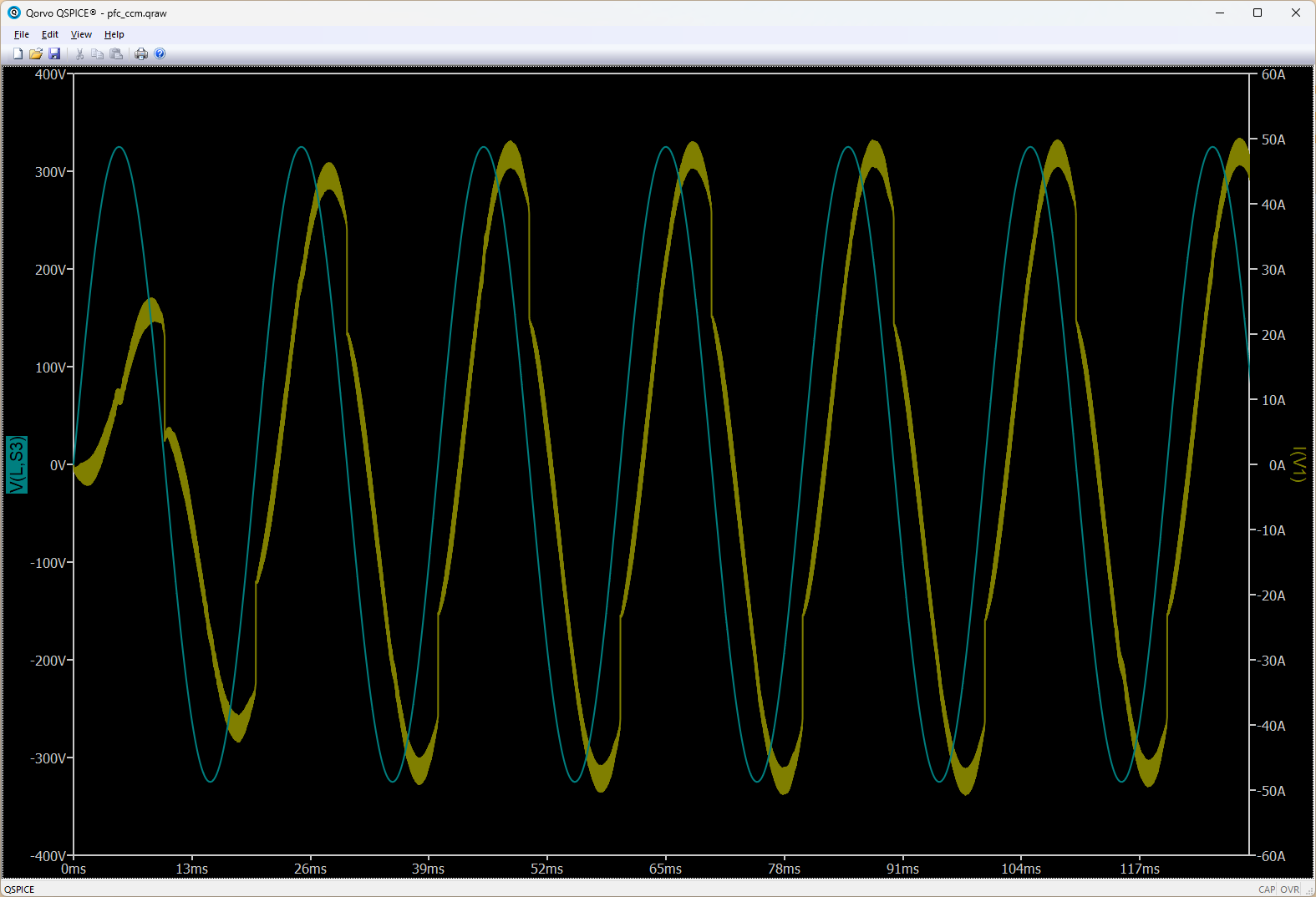
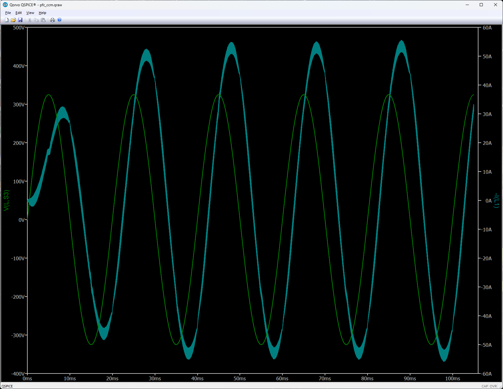
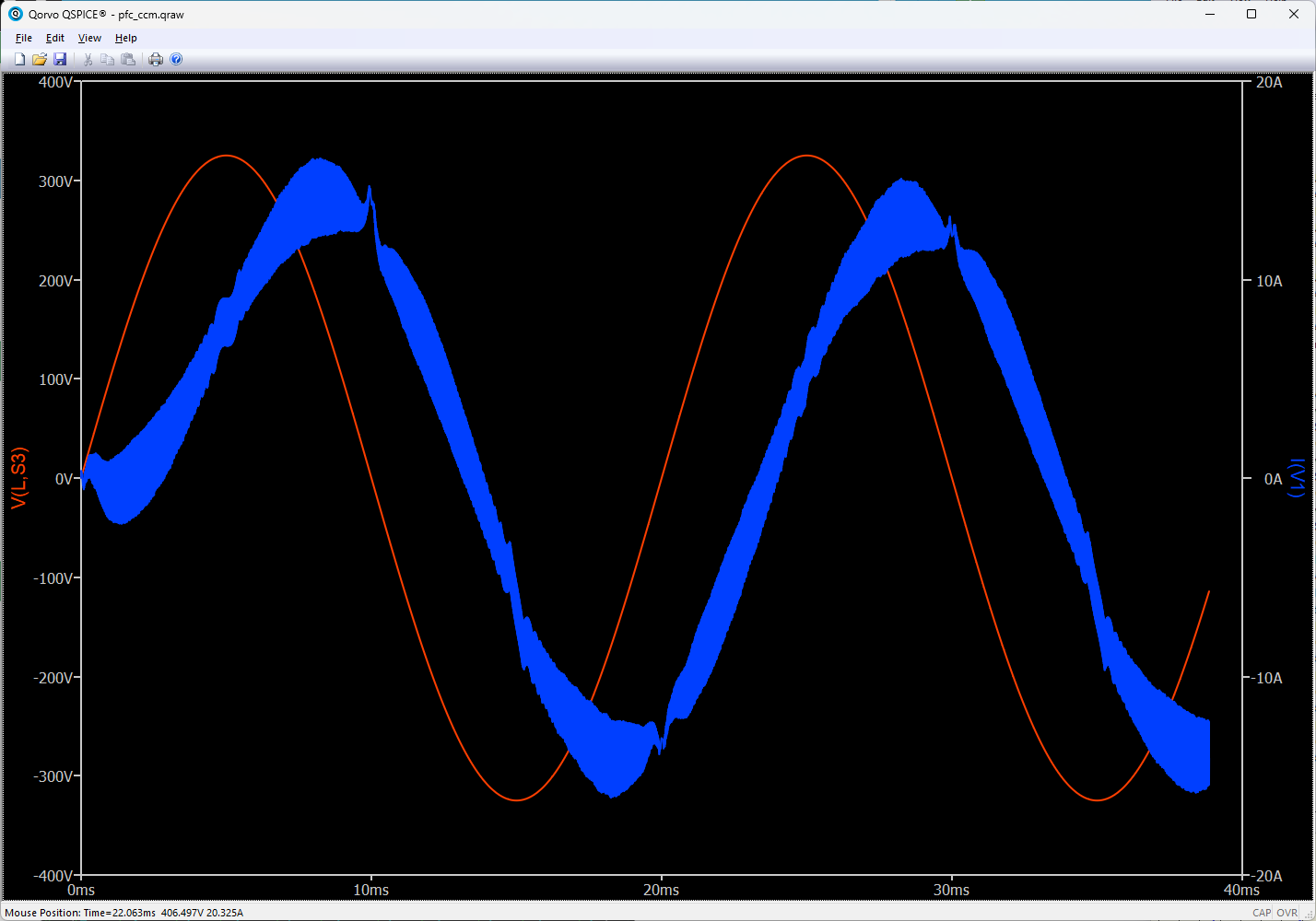
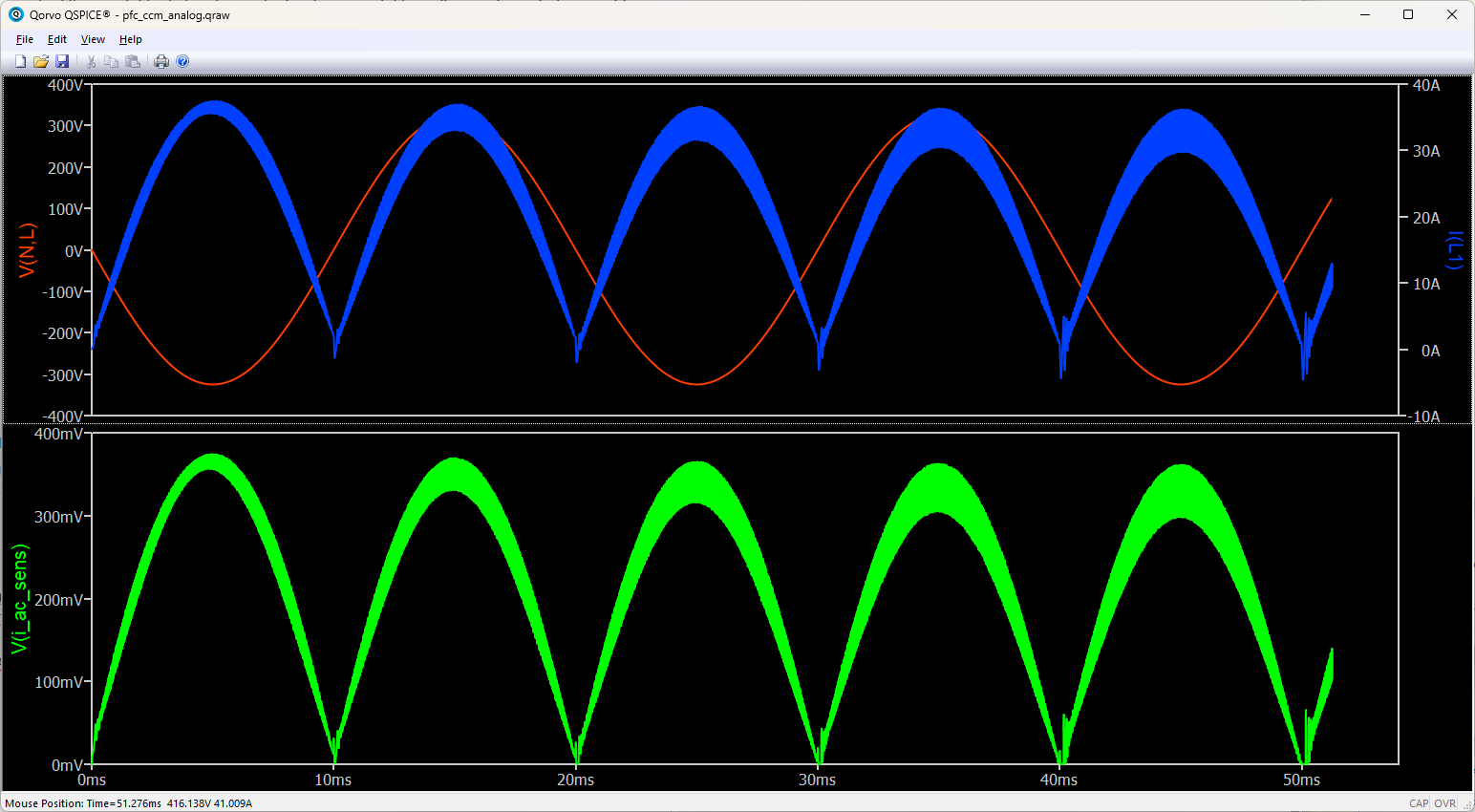
My feedforward alone shows wave current that i think is not correct. See below with anly the feedforward.
// Automatically generated C++ file on Wed Jul 15 11:30:01 2026
//
// To build with Digital Mars C++ Compiler:
//
// dmc -mn -WD -o mcu_calc_2.cpp kernel32.lib
union uData
{
bool b;
char c;
unsigned char uc;
short s;
unsigned short us;
int i;
unsigned int ui;
float f;
double d;
long long int i64;
unsigned long long int ui64;
char *str;
unsigned char *bytes;
};
// int DllMain() must exist and return 1 for a process to load the .DLL
// See DllMain entry point (Process.h) - Win32 apps | Microsoft Learn for more information.
int __stdcall DllMain(void *module, unsigned int reason, void *reserved) { return 1; }
// #undef pin names lest they collide with names in any header file(s) you might include. #undef Vac_in #undef Iac_in #undef Vout #undef PWM_H #undef PWM_L #undef SYNC_H #undef SYNC_L #undef clk #undef tmp #undef tmp2 #undef tmp3
extern “C” __declspec(dllexport) void mcu_calc_2(void **opaque, double t, union uData *data)
{
// Inputs
double Vac_in = data[0].d;
double Iac_in = data[1].d; // Dit is je gemeten stroom
double Vout = data[2].d;
bool clk = data[3].b;
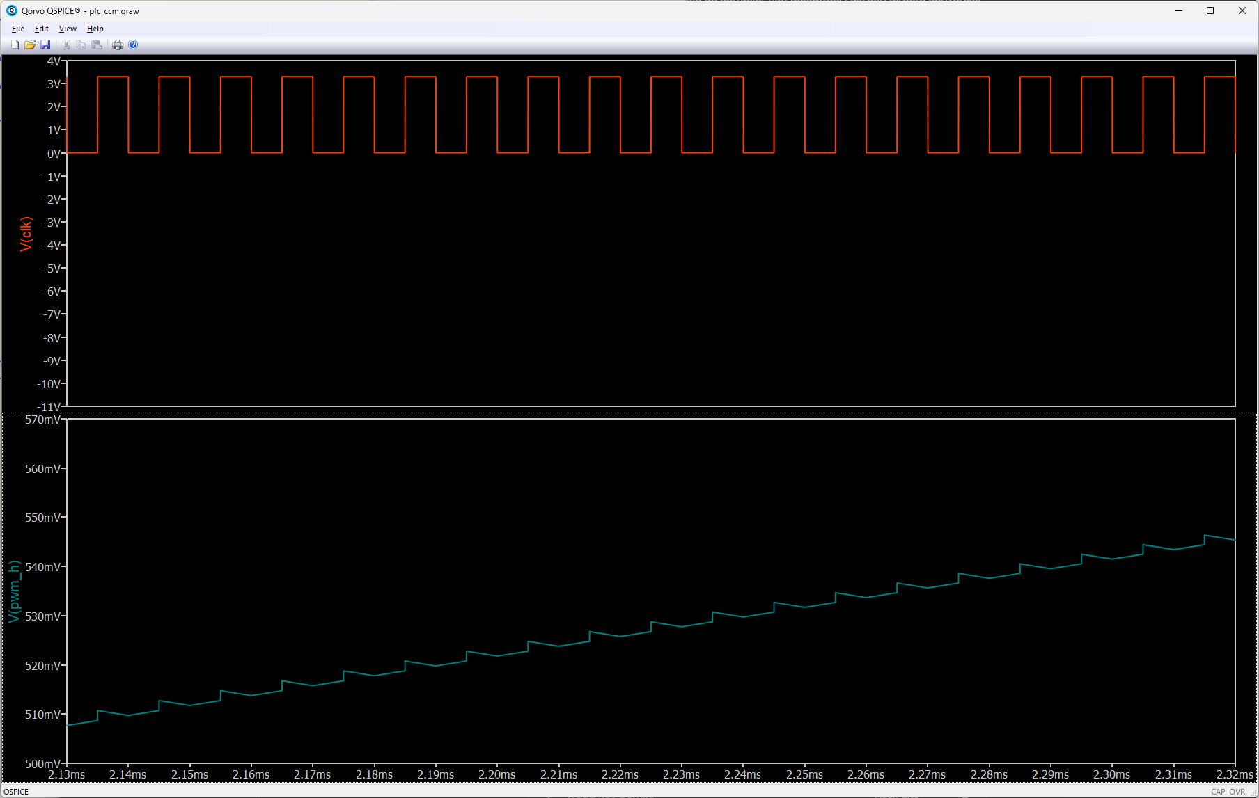
I delay my clk pulse block so it matches with the middel of the triagle. the waveform is a lot better. But i still do not understand the phase delay. That is so big.
I made many power conveters in the past including DAB etc(from few 100W up to 50kW. But mainly the power stage, topology and magnetics part. Digital control i have limited experience with but i want to learn this more.
That said, i want to use this to set up digital control. BUt want to have it working first ofcourse.
Would you mind helping me change my code to make it better suited ?
ps. My control does not work well because i invert the duty in the output code. This means that the second part of the sinewave, the control operates the wrong direction. I think i should take the direction outside the block for now.
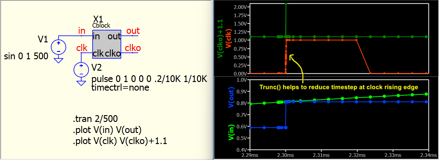
He needs an external clock, and the correct way is to include Trunc() for hypothetical calls.
His schematic has ¥-Device, which by default includes TTOL (equivalent as Trunc()). So, I guess skipping hypothetical calls may mess up the whole thing…
Here is code to demonstrate sampling V(in) at every rising edge of V(clk) by including Trunc() to reduce the timestep to TTOL at the rising edge.
In this example, I added timectrl=none for V2. The purpose is to remove the timestep control algorithm in V2 so that I can clearly demonstrate the use of Trunc() in this C code only modify rising edge, and not at the falling edge. If timectrl=none is removed from V2, you will see the timestep also reduce at the clock falling edge, as V2 has its own timestep control to help reduce the timestep at transitions. Cblock.qsch (2.5 KB) cblock.cpp (5.0 KB)
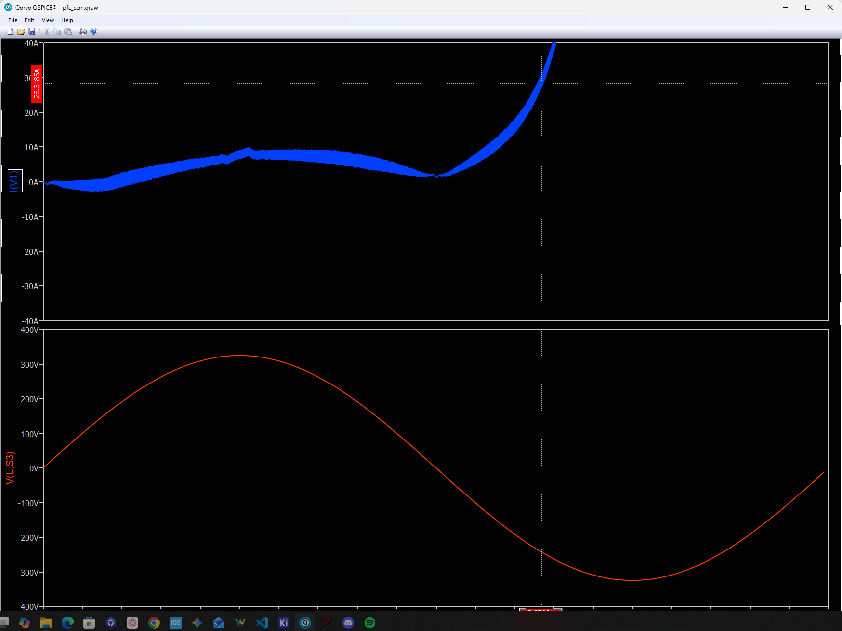
thank you both for helping me out. I used the code from Kelvin and put it in mine. I do see some behavior i did not expect. See below for the waveform. I am sampling at 100kHz but there is a change in value during the cycle. I would expect a more block wave if you will. Any idea how this happens? mcu_calc_2.cpp (7.6 KB)
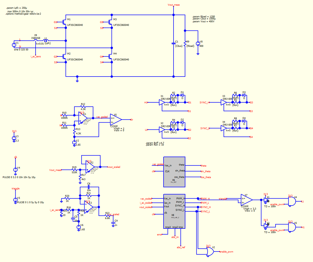
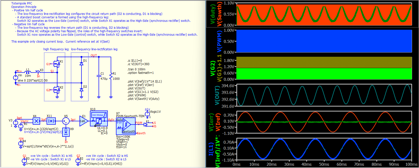
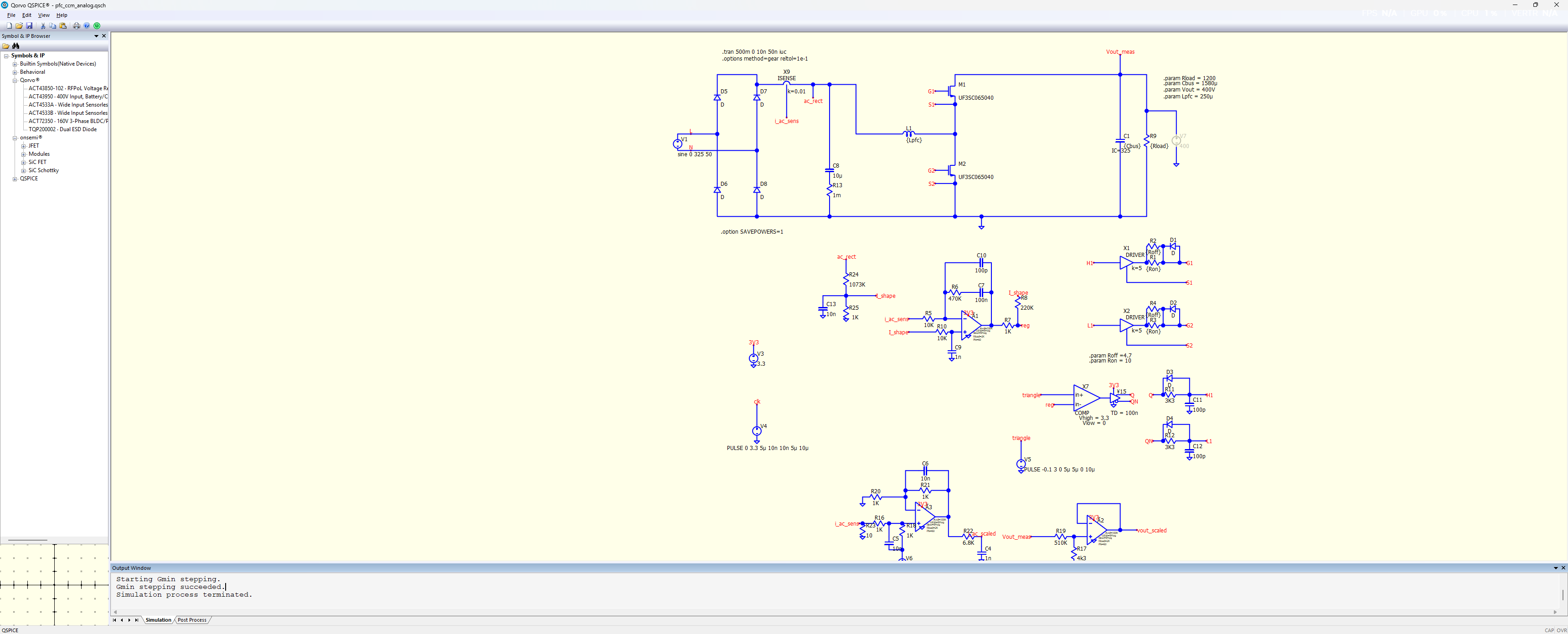
I cleaned up a little and took out the polarity change in the code and used logic blocks. Getting the same feedforward effect so that seems the same. But still not current controlled and get strange behavior i dont understand . pfc_ccm.qsch (67.1 KB) mcu_calc_2.cpp (7.8 KB)
Thaamike, It would help us a lot if you could simply write down the control equations that your are trying to implement for the pulse widths in algebraic form. (such as: Duty = K*sinVac . . . etc etc) first instead of the code to implement the control equations. It looks like people are suggesting canned code with no understanding of what’s in there.
Well i want to keep it simple to start with and use only a closed current loop.
At the moment i only have feedfoward that is a rectified sinusodial shape. I take the abs value of both voltages and currents.
My plan is using a slow PI control first. Meaning i take the error between measured and ref current and put that is my pi. output is between 0.1 and 0.99 and is compared with triagle waveform that go’s from 0 to 1.
I make the current ref by multiplying the rectified ac voltage.
@thaamike Did you have a working analog model before you implemented the C++ model?
I cannot run your code because you included a subcircuit that needs MyLibrary.lib, and you didn’t upload that file.
A totem-pole PFC is a topic I am not familiar with. For a new topic, my approach is to build an analog model and verify everything step by step after learning how things work fundamentally. Once the analog model works, you can move forward to C++ code for the controller.
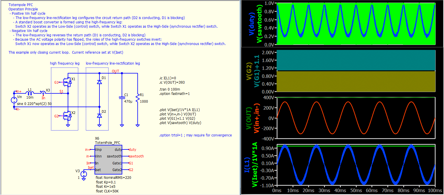
I didn’t close the voltage loop or implement discrete sampling in this code, as by the time I reached this point, I had already spent a few hours on it. I hope this can be a starting point for anyone who needs to work on a totem-pole PFC in QSpice.
I recommend that you use ideal devices for the initial implementation. After you get things working, you can step by step replace parts of your circuit with semiconductor models.
Thank you for the time you put into this. This will for sure help me . I already spend days in this trying to figure out what i’m doing wrong. I’m to green in this simulation part.
Somehow i always have difficulties with simulations…
I tried a simple pfc stage boost and get some osscilation near the zero crossing for example.
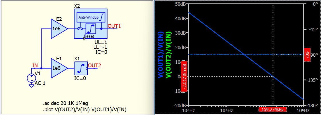
Here is the Bode plot of an integrator with 1e6 gain, where its crossover frequency is at ~160kHz, which is roughly the switching frequency in this example. You might wonder why this number is so large, but an integrator gain between 1e4 and 1e6 is actually quite common for an SMPS.
In my experience, the easiest way to tune a PI controller is to first apply the I gain with the P gain set to 0. Increase the I gain by orders of 10 to check the response. Once you have a good enough I gain, move on to applying the P gain. The P gain generally starts from a very small number (e.g., 0.01) and is increased to see the response. Of course, the best approach is to obtain the open-loop response and design the controller, but it is also common to tune it blindly, as that is the beauty of a PI controller.
Most importantly, I actually don’t know how to measure the open-loop response of the current loop in this totem-pole PFC. If anyone knows how to do that, sharing it would be very helpful.