Thank you for you explanation. Normally I would indeed or in the real world tune the type 2 compensator or need to loop response. It would be interesting to see the closed currentloop for this because it would think the closed loop with this integrator is very high. Normally for the pfc current loop I would expect a few kHz for the Fcross
Type II is just a PI controller with a high-frequency pole. However, Type II uses the form of two poles and one zero frequency, meaning you normally do not calculate what the integrator gain in equivalent to PI.
Anyway, if you work on Type I, II, or III compensators, you might consider downloading my custom symbol library. I created these three compensators in op-amp subcircuit format where you only have to input the pole and zero frequencies, and it automatically calculates the corresponding resistance values. Tuning Type I, II, and III compensators is tedious if you have to recalculate the component values every time, which is why I made these custom symbols.
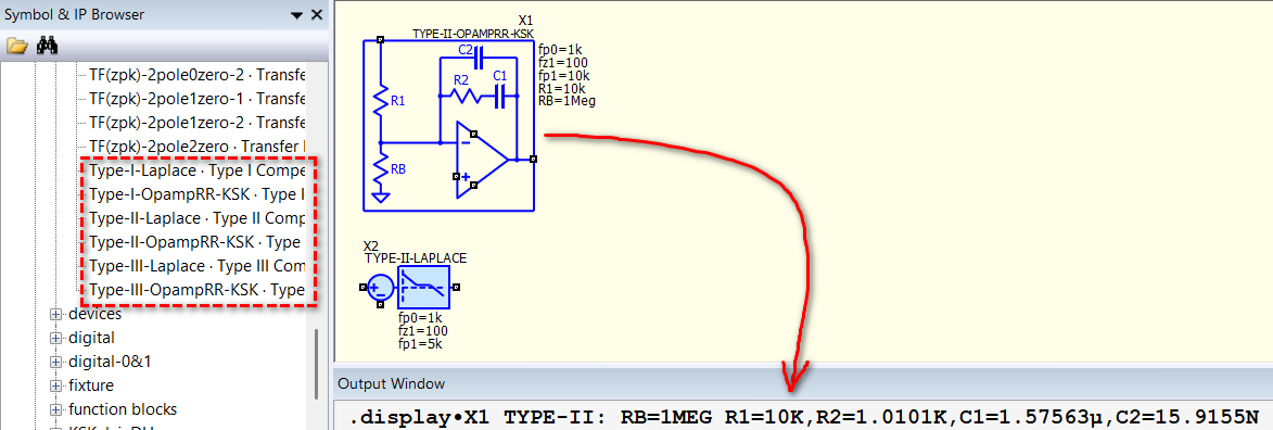
Yes it has a known curve and high frequency attenuation. Normally depending on the open loop, I design the poles and zeros. Using python script to calculate the values every time. But interesting that you already made something in qspice. Trying to learn and use Qspice more and more so this is interesting to have.
I see you are a master in qspice ^^
1 Like
Hi KSKelvin,
did you tried to use it as a 3 leg interleaved totem pole pfc for 11 kW ?
that’s something i am working on directly with VDMOS model, but it is still tricky
BR
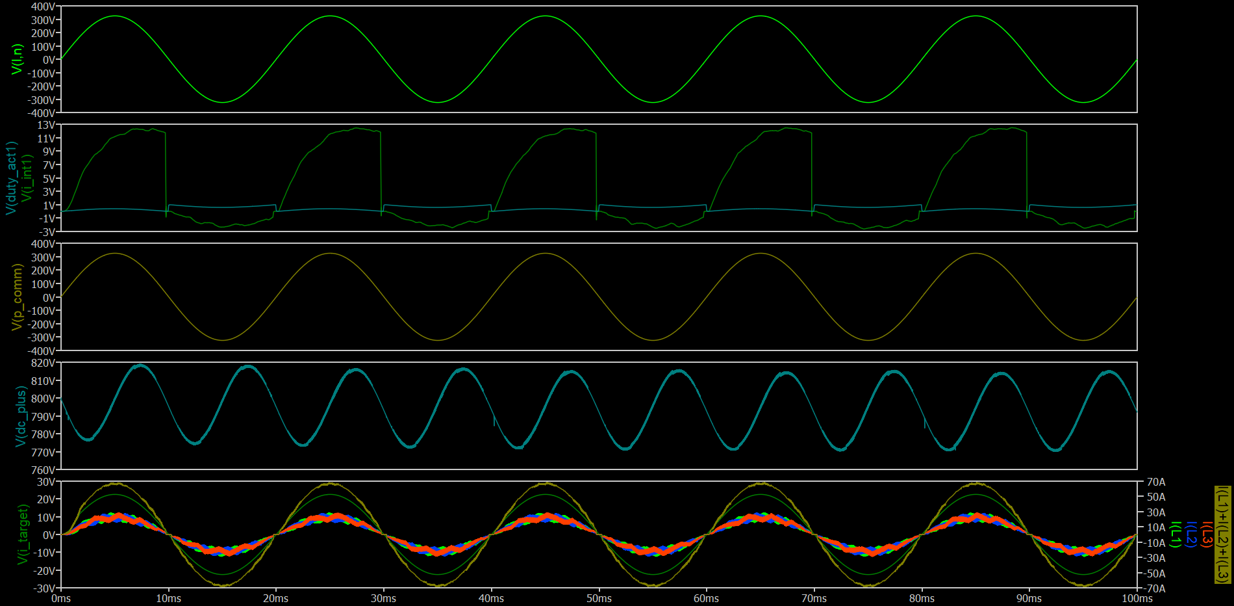
,
Reda
what is the problem you encounter?
here I just modified C++ code to support single phase 3-leg interleaved totempole PFC.
3-channel Interleaved Totempole PFC (C++ version).qsch (31.7 KB)
totempole_pfc.cpp (9.5 KB)
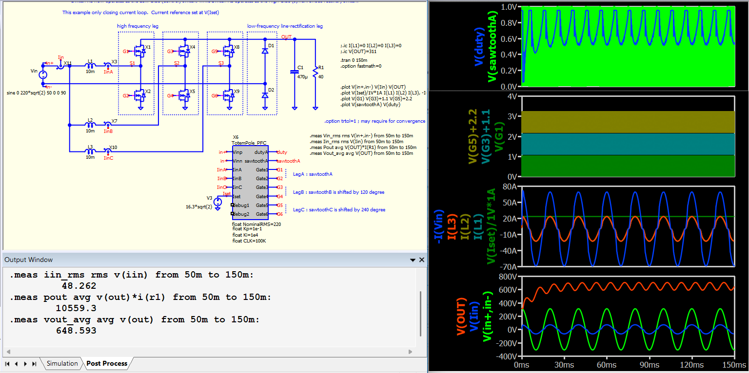
Thank you for the quick response. The simulation worked well with ideal components, but tuning the closed loop became challenging once I added real-world characteristics as usual for power electronics, as a new User in the community, I am not able to upload files besides one image !
Thank you very much!
This is how you can increase trust level to upload schematic.
https://forum.qorvo.com/t/qspice-forum-new-user-to-basic-user-file-upload/24340
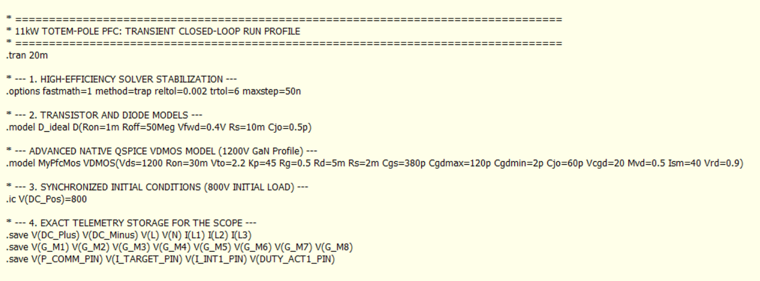
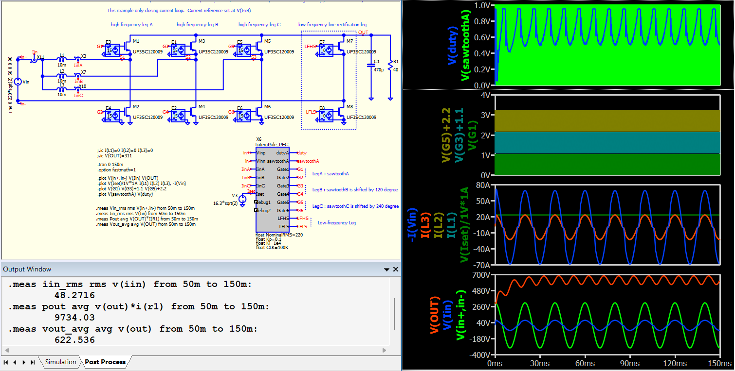
I replaced the ideal switches with VDMOS models from the QSpice library. At this power level, the low-frequency leg requires synchronous FETs, so I updated the C++ code to generate the necessary gate control signals for them.
You created that GaN model? There are multiple parameters not support in VDMOS in Qspice, for examples, Vcgd Mvd, Ism and Vrd.
3-channel Interleaved Totempole PFC [FET] (C++ version).qsch (36.7 KB)
totempole_pfc.cpp (9.9 KB)
thank you for the support! I will take my time then to understand more about the trust levels.
I took what you have send before as schematic and code and to be able to keep track on the DC Output voltage of the desired 800 V DC, I am using cascaded closed-loop control, that is better when moving from 1-channel to multi-phase interleaved totem pole pfc.
Here is the results.
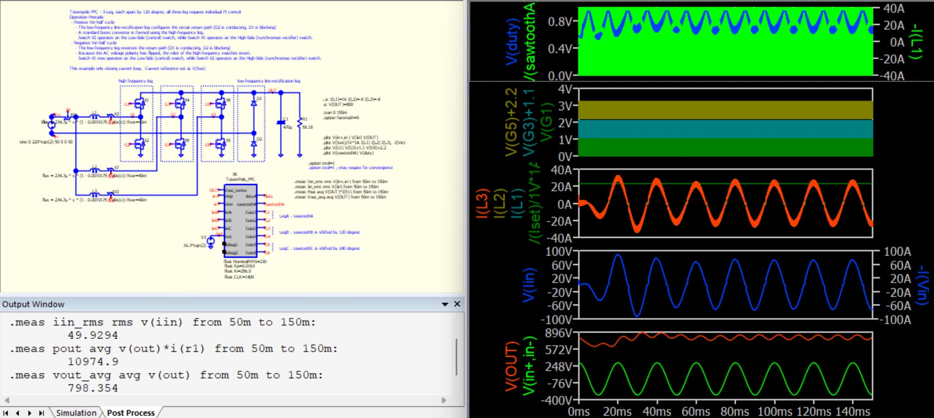
About the GaN Model I was trying to tune it for specific rise and fall time of about 60 to 80 V/ns based on other third GaN Models.
You modified the code for cascode control?
Wait to see you increase your trust level and share your work. It would be great if more member to share their work if it is not confidential. Definitely help this community. I didn’t close the voltage loop as I said in previous post, I am really not an expert in totempole pfc. I learnt that only after I saw these questions.
If you don’t sense the output voltage to the control then you will not be able to have the outer voltage loop because in the cascade control structure you have the outer slow loop and the fast unner current loop. that is why you only get less than 800 V. I am only doing a reasearch about the optimization of real power electronics so that is why an ideal simulation is worth a start but further I need the finetuning.
right, final complete version requires to close the voltage loop. if you not familar with using Dll block yet, may be you can use analog block to close the voltage loop and feed it into current setpoint.
yes right, thats what I did on the post before if you see my results, I have an avg output voltage of 798 V DC. Plus a non linear model of PFC Chokes. I sensed the output voltage, but things getting hard when I am trying to tune rise and fall time of specific GaN model. I am not familiar with VDMOS models.
Normally, the voltage feedback can simply be closed loop with a PI controller.
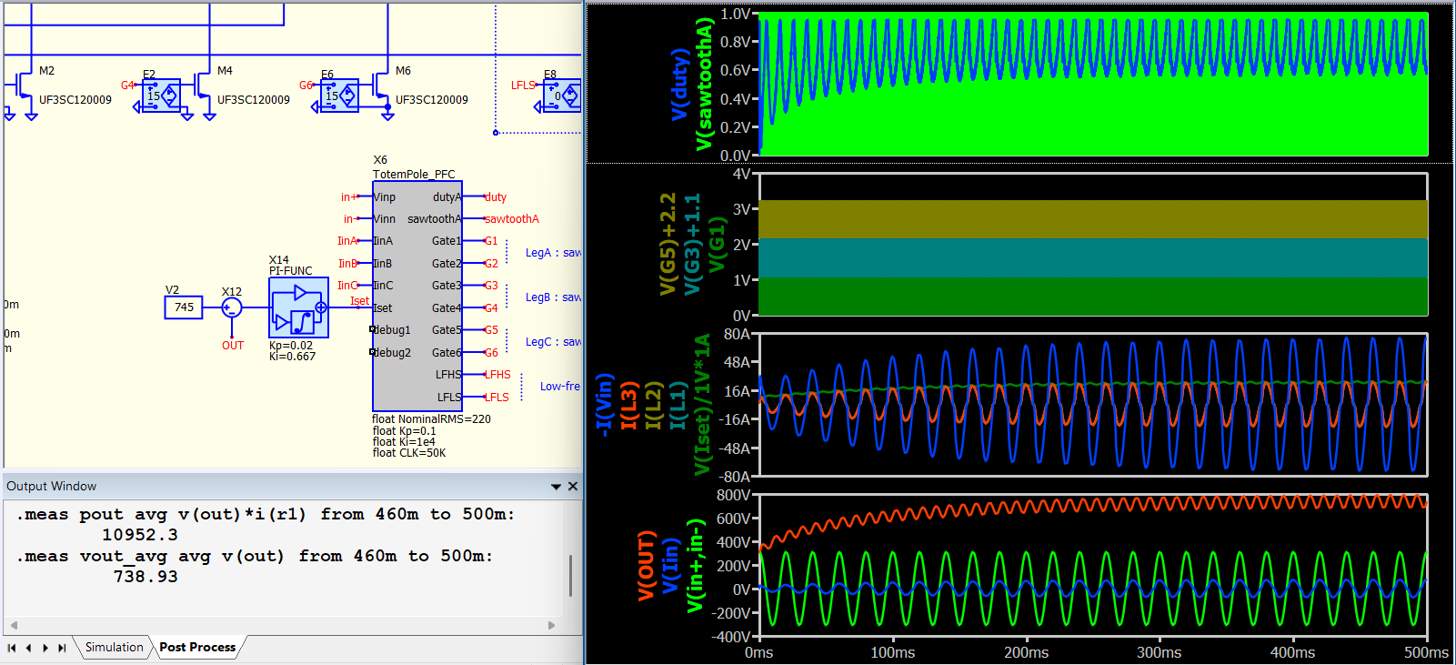
Here I put this into my VDMOS model example. Increased simulation time to 500ms and reduce switching frequency to 50kHz. I just don’t want to wait too long for a simulation. Higher the switching freq, more time for the simulation to run.
For simulation, you better make sure one thing work before putting other thing in. One thing as a time.
3-channel Interleaved Totempole PFC [FET] (C++ version).qsch (39.2 KB)
totempole_pfc.cpp (9.9 KB)
Thank you for clarification.
If you see my last screenshot I started with .ic V(OUT)=800 and I got an average of 798 V. this was fast.
this time I like to try it with the synchronous switching leg, still strugle ot get the right parameters to run it at 140 kHz.
first thing i kept it as it is ramping up the output voltage from 311 V.
3-channel Interleaved Totempole PFC [FET] (C++ version).qsch (39.3 KB)
totempole_pfc.cpp (9.9 KB)
Hi all,
Maybe someone in the community has run into this problem before when modeling MOSFETs. I’m new to modeling in QSPICE, and I still have the LTspice workflow stuck in my head.
pfc_c_driver.cpp (16.5 KB)
1Ph_3LITT_PFC.qsch (69.8 KB)