A contribution to people who use STM32CubeIDE (I don’t know way Qorvo does not explain this in the API guide !!! )
- Add in the linker script what is told in the API guide
/* The program code and other data into “FLASH” Rom type memory /
.text :
{
. = ALIGN(4);
__dw_drivers_start = .;
KEEP((.dw_drivers))
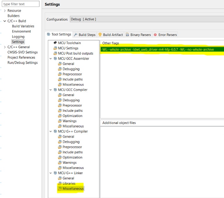
__dw_drivers_end = .; - Do not include the static library in the regular way, IT WILL NOT WORK! Do this instead (in my project I am using M4 core so I picked the suitable API library)
Image2|565x500
Image1|690x441
So you leave Libraries (-I) empty BUT in MCU G++ Linker Miscellaneous you add in “other flags” what is shown in the picture (remember to use a suitable API library for your core)
That´s it, easy if somebody tells you. Qorvo, why don’t you?