However, unlike them, the DWM always returns 0xFFF…, no matter the circumstances. I’ve tried using an arduino (with 3.3V logic) and an stm32, but neither worked. I’ve also tried sending different character “0x00” and “0x40 00x02” but to no avail. I’ve tried changing the phase, adding a delay between the pull-down of nCS and the hal transmit function, pulling reset low between tranmissions, and lowering the frequency below 1 Mhz. Every single time, I’ve received 0xFFF…
Beyond the obvious problem with the SPI set-up, I couldn’t find any hint in the datasheet, the user manual, or the debugging application note. At this stage I’m pretty confident the problem has to do with the module not receiving the buffer’s content properly, nevertheless I don’t know what could have went wrong.
I’ve tried everything I could think of. If you have idea of what I should try next or what could have gone wrong, please let me know.
If you hold nCS low, hold MOSI low and toggle clock 40 times you should get 0xFF followed by the device ID on MISO. If you don’t there is some fundamental hardware issue with the way the module is connected. The first places I’d check would be that:
The SPI bus is wired correctly
The reset line is wired correctly (from memory you should be able to leave it unconnected, it should idle high but pulse low on startup)
The power supply is the correct voltage, all the VCC and GND pins are correctly connected and that the supply can source sufficient current.
Don’t trust the firmware that the SPI / control pins are all doing what you expect, check them with a scope.
-Yes, I thoroughly checked power delivery. Everything seems fine (voltage and current wise).
-I also checked my wiring a thousand times.
-Unfortunately, I don’t have a scope on hand at the moment. However, I did look at the SPI lines with a logic analyzer, and I saw nothing abnormal (clock looked fine, the packets were sent correctly to the DWM, the MISO line transitioned from low to high, etc.) (I wish I could take a screenshot, but I don’t have the logic analyzer with me at the moment).
Finally,
I’m currently using the HAL libraries for SPI, so I don’t have precise control over timing. I did try this in my own way by using a buffer with 0x00s and a very long receiving buffer, but it doesn’t seem to work. I might try to implement this from scratch later.
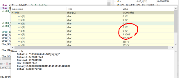
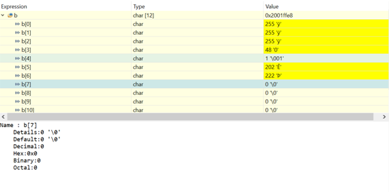
Edit: With a delay of 1ms between nCS pull-down and the HAL_Transmit function, there seems to be a different behavior. Other transmission events where I didn’t use a delay only yielded 0xFF in the buffer.
That is very odd. I set the CS low and then call the SPI write function without any extra delay beyond the delay imposed by the SPI write function call and it works reliably with the SPI clocked up at 20 MHz. Certainly no need for any significant delays in there.
Can you post schematics / layouts of that section of your board or is it proprietary?