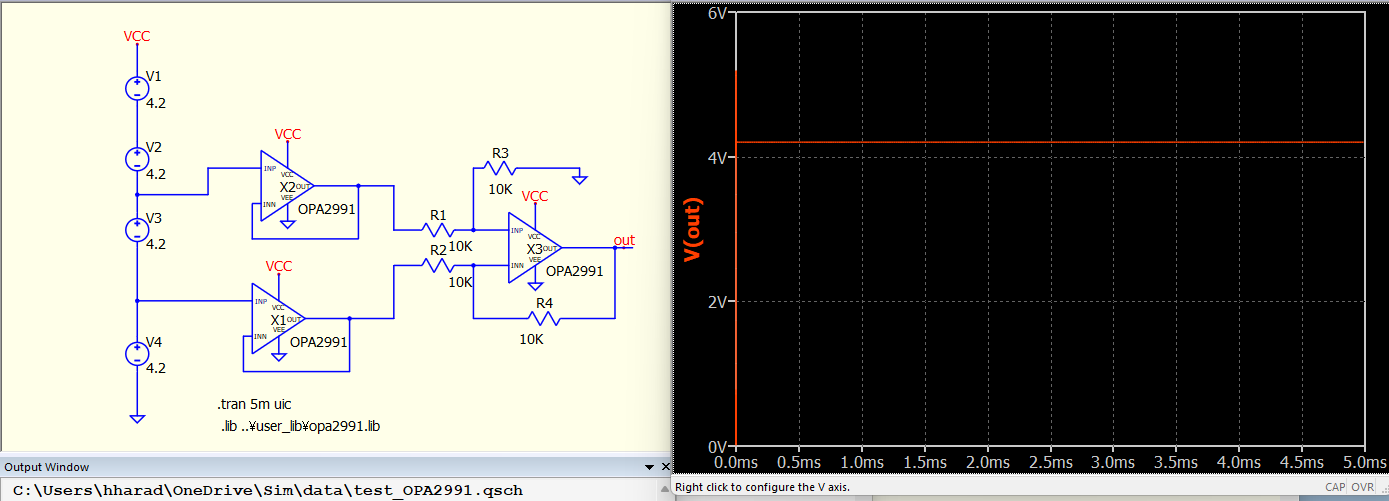
I’m slowly getting the hang of Q Spice, and have limited experience with other circuit modeling software. I keep getting a “Gmin stepping failed”, and “Pseudo transient analysis failed at t=0” errors. If i change the value of R4 to 1k it simulates just fine, which doesn’t make sense to me. Basically putting together a multi cell voltage monitor with buffer and diff amp to feed to ADC… I plan to scale this for an 8s pack, so this is only about a 1/4 of the circuit… I’ve gotten the same circuit to sim just fine in LT spice, so not sure if i am doing something wrong here…
Apologize for the delayed response. I appreciate you taking a look at this! Unfortunately it will not allow me to upload files as i am a new user… I can tell you that i pulled the spice model directly off of the T.I. website - I used the P-Spice Lib file that was in the zip folder and followed the import instructions from the Qorvo YouTube videos. It seems to function fine without the buffer circuit before the difference amplifier, but fails with both. As far as i know that there should be no issue with this OP amp and a single supply.
I’m not sure what is going on, could it be an impedance issue with the buffer before the difference amplifier? I’ve tried the same circuit with a few other T.I. OP amps that should work for this application and get the same error… I’ve tried the TLV 9152, and TLV 9352 as well.
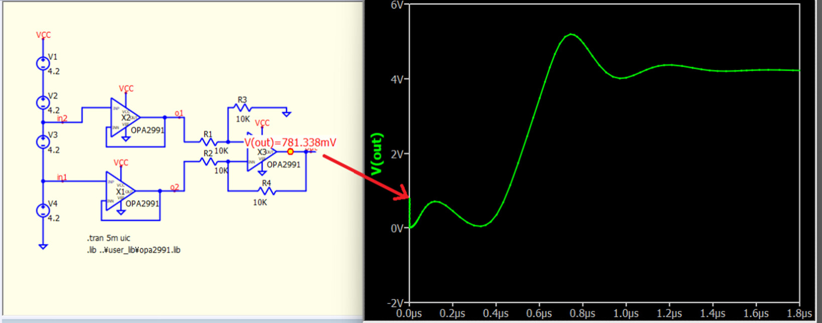
I appreciate the suggestion! So I was able to get it to run with the “uic” added to the directive, however i still get erroneous readings when i probe the schematic directly at the out of “X2”. Just curious, what does the “uic” function do?
I can get this exact schematic to simulate in LT Spice, but it takes a ton of time… Even with my 12 core CPU and 32gig’s of RAM… Qspice seems much quicker, but tones of issues with various components i have imported related to this schematic. I have tried several OP amps and almost always get the same error…
UIC is Use initial conditions instead of solving for initial bias point. For spice, in .tran simulation, if UIC is omitted, it will firstly calculate dc operating point voltage and use that calculation to begin simulation. UIC force everything to start from 0V except you specify a node with .ic. (In short, it skip .op before a .tran begin)
So, the major problem when without UIC cannot work, is because currently this schematic failed in running a .op simulation. I run this same netlist in LTspice but without problem.
At this moment, you can firstly consider to give a negative voltage and this circuit should calculate .op without problem.
Interesting… Very obvious I have a lot to learn on the sim side… Thank you very much for the detailed explanation. I will try the various OP amp’s i was considering with the same negative voltage as described and see how they compare.
If you wish to obtain a DC operating point, it would be advisable to use the “.op” command.
Initially, “QSPICE” did not converge, but after the update on December 8, “QSPICE” successfully converged with the use of three “.nodeset” options.
As @EL34 comment, Mike made some improvement to Qspice in handling TI non-physical opamp pspice model, which consist of many lookup table and switches.
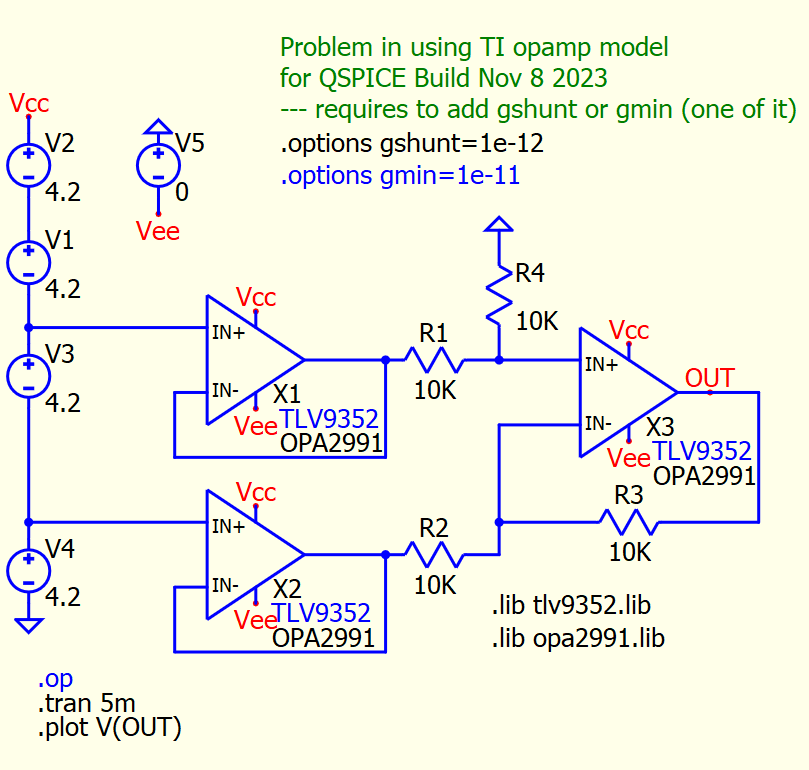
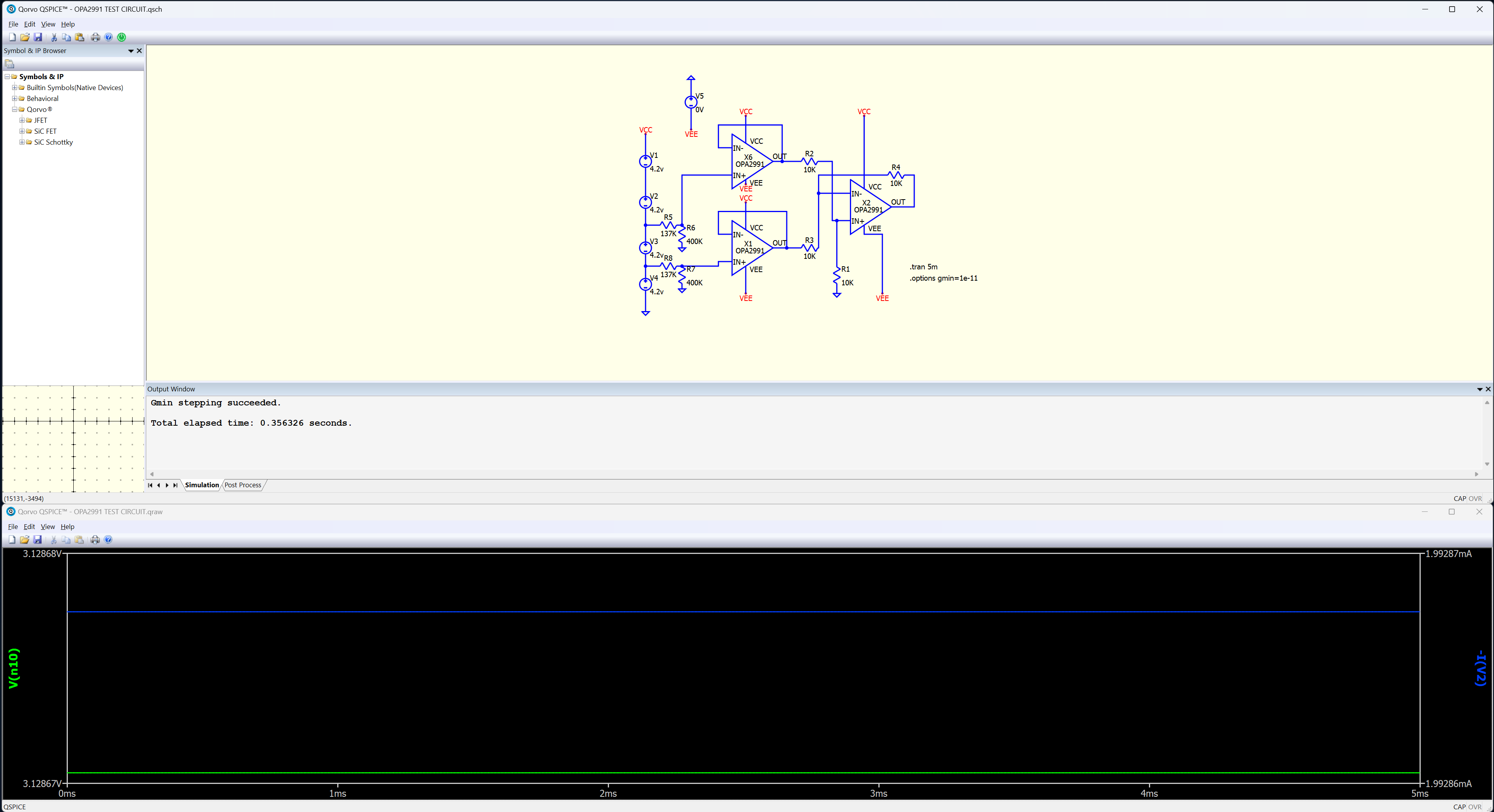
After update Qspice to latest version, please add one of these .option .options gshunt=1e-12 .options gmin=1e-11
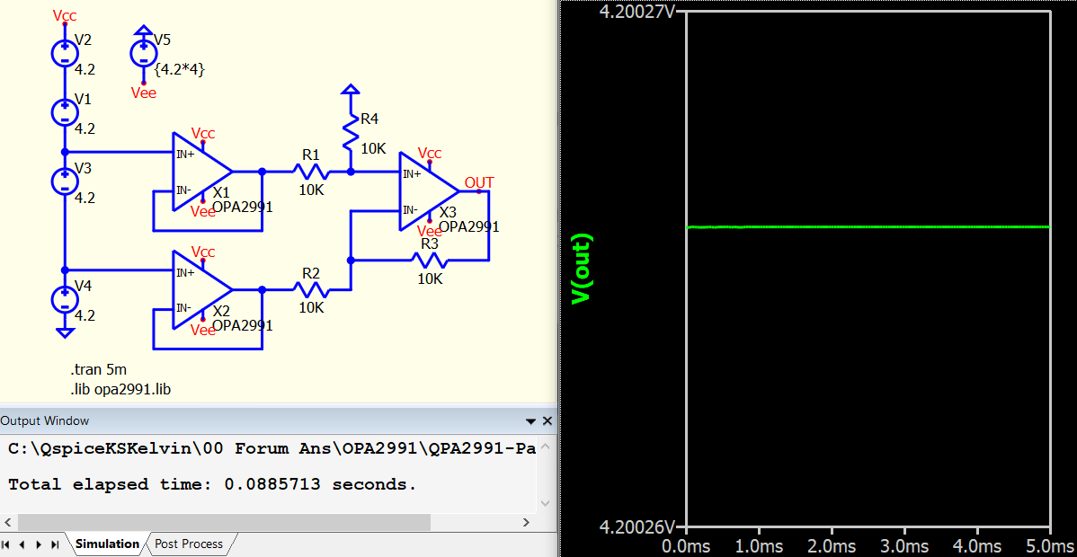
I verified this with OPA2991 and TLV9352 from TI library, with Vee set to 0V.
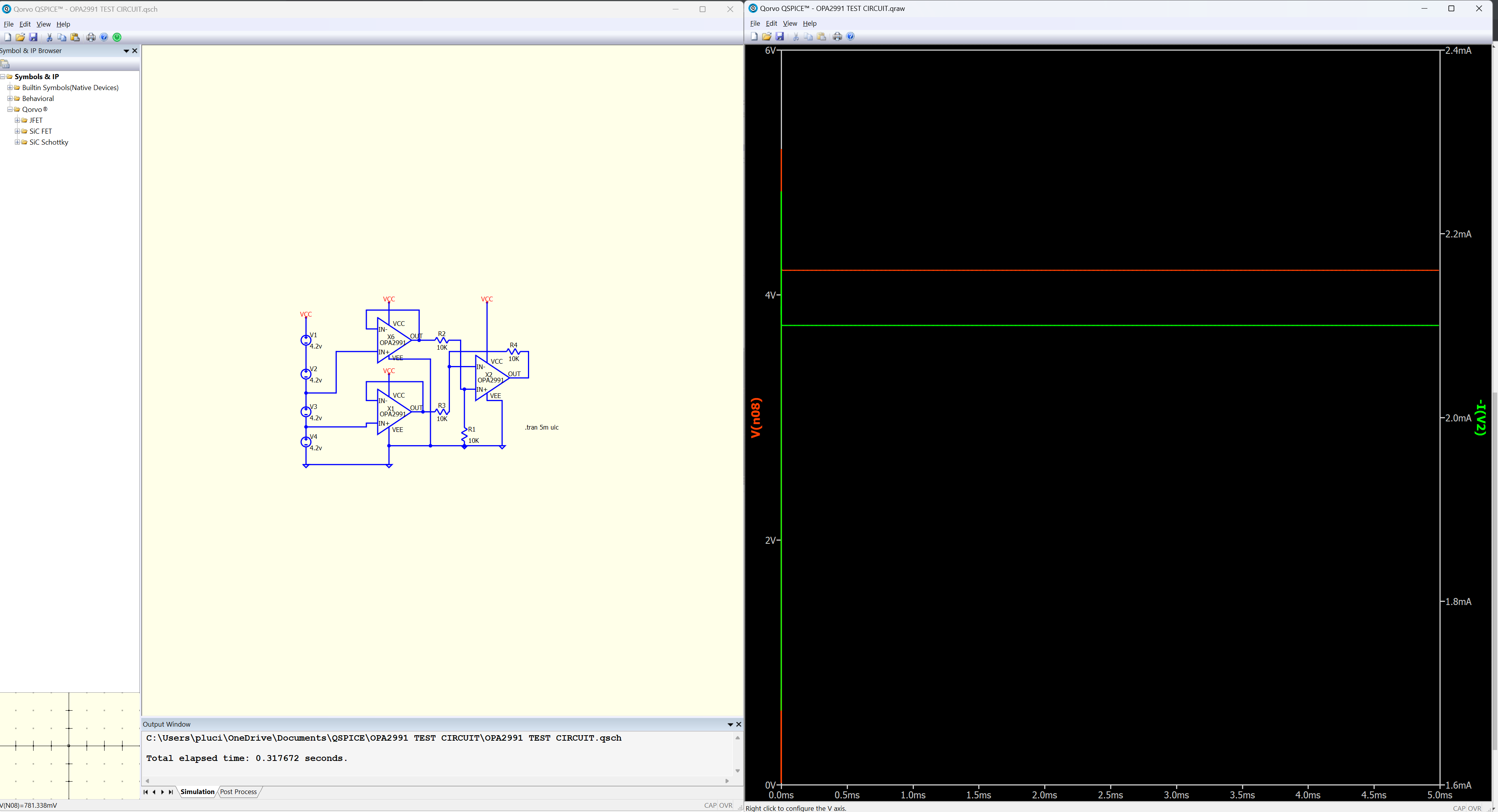
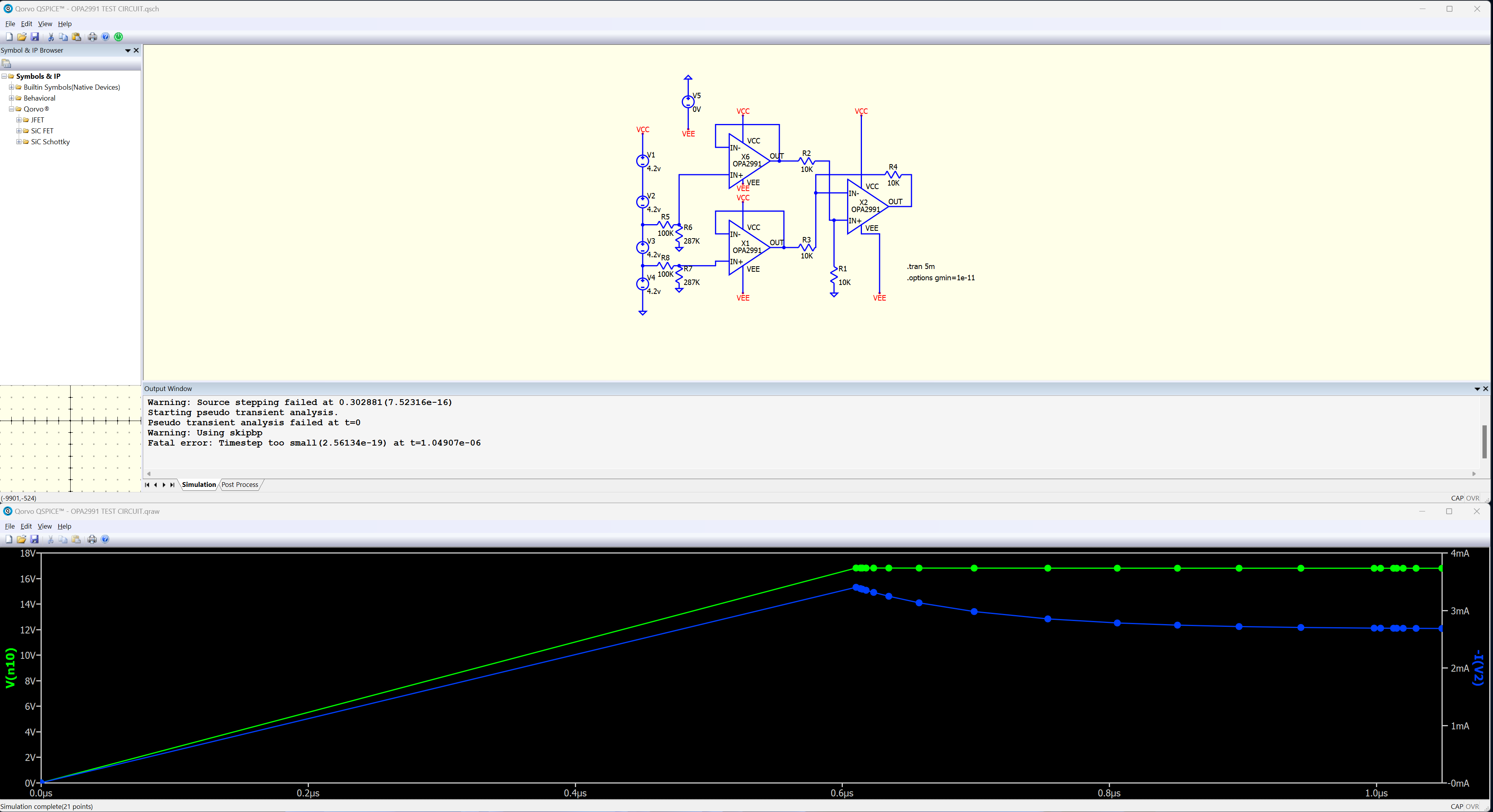
@KSKelvin I appreciate your follow up, and Mike assisting with this. Apology for delayed response - I had a family emergency come up. So I was also able to verify that this now simulates correctly with multiple OP amps, however as i continued to build the final iteration of my circuit, adding a simple voltage divider pre-buffer, the simulation only works with specific resistor values, but most combos fail… Do you know why this might be happening? Screen shots attached for example
The challenge is still in handling .op calculation for this type of TI opamp model in Qspice. Change to skip .op as initial condition (i.e. .tran 5m uic) that @EL34 suggested is the most easy way to help this circuit to run in Qspice currently.
If you don’t want to see transient result before calculation reached steady state with uic added, you can modify the .tran into .tran 0 5m 1m uic