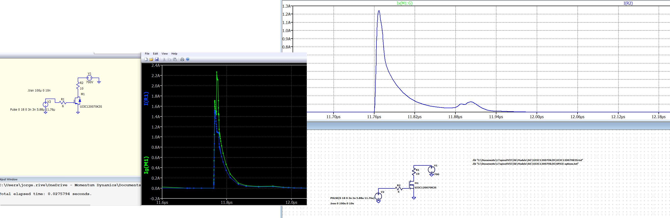
I tried a simple circuit and was confused by what I saw in the sim results. Basically, it is a voltage source driving the gate of a SiC Mosfet (I was looking to see if the sim matches the leakage currents I measured with an SMU on a physical device), and the current through the gate resistor does not match the current into the gate (??).
So, I simulated it LTspice, and I got the expected result where the current through the gate resistor and the current into the gate are the same:
The model in Qorvo is “device model”, while it is a “subcircuit model” in LTspice. Perhaps that is the source of the difference – is Qorvo’s model is modeling something the Spice subcircuit model does not ?
I apologize–couldn’t figure how to include the circuit file in here, and it also complained about embedding multiple files, so I had to combine screenshots into one image.
The current monitored by the resistor(or V2) was the correct one. That was the current going into the gate.
Current monitoring of transistor terminals is very nice feature, but the simulator never solves for them. They are reported in a forensic analysis after each simulation is step complete.
There was an error in this forensic analysis in QSPICE, so there was a fairly small error in the reported current. It’s fixed now. Do an update and the current measures by the resistor or Ig(M1) will match as they should.
after reading this post, Looking for How-To document, I tried to measure the instantaneous power across the cascode in this circuit by using cntl-left click. It returned P(M1) = ~81W. But, when I calculate it by using Id * Vds (Id(M1)*V(n02),where n02 is the node between the drain and R2), it plots ~176W. Bug, or am I not plotting what I think I am?
QSPICE has the ability to compute the power dissipated in the FET.
It doesn’t sum the integrated Poynting vector over all ports(which your expression is attempting), but the actual heat-causing dissipation, i.e., the device equations are sorted out as to what is dissipation and what is nondissipative displacement current in the reactances.
But you have to enable by adding
.options savepowers=1
Then you can plot dissipation by Ctrl-right clicking on the FET.
It isn’t turned on by default because it bulks up the datafile and invokes some additional compute overhead.