Hi , can anyone guide me how to get output from .dll block at a fixed sampling time? Any relevant resources would help guiding me through using small example.
The evaluation function should be regular intervals, i want digital implementation.
SPICE uses dynamic timestep; the idea is to execute the algorithm when the timing condition is met (in your case, at a fixed period), making your DLL-block behave like a fixed step update.
Getting a DLL component to trigger a simulation sample point at precise intervals (or specific time-points) is tricky as @KSKelvin’s references describe. In early efforts, we used an external clock (pulsed voltage source) to drive a component input port expecting QSpice to take samples when the clock state changed. It seemed to work until we discovered that it was unreliable. QSpice is very clever, contains dark magic, and sometimes undoes otherwise obvious solutions.
If you’re new to DLL component development, I suggest that you check out the C-Block Basics papers in my QSpice GitHub repository. For this particular question, I think C-Block Basics #5 may help. It’s the most reliable method that I know of to get QSpice to take samples at specific simulation time-points.
@RDunn Interesting… It depends on the situation where an external clock is present in a circuit. Sometimes, the external clock is used to sync all digital elements and may not be eliminated. Therefore, during the PID project, I stuck to the traditional approach to implement digital PID with an external clock as this can be more universal. With an external clock, as the occurrence of the rising edge is NOT predictable, it relies on the standard ttol approach with Trunc() to verify if a future event may trigger a change and to determine if the timestep needs to be reduced before rising edge to make sure the transition is captured.
In C-Block Basics #5, the exact time to sample or event is known. Therefore, the time to the event is deterministic, and thus, your algorithm dictates that the simulation timestep should be equal to the time apart from the event. Immediately after the event, the timestep is drastically reduced (referred to as inst->ttol, fed from MaxExtStepSize()). Unlike the previous method, this approach does not require reducing the timestep before the event, but it is only feasible for deterministic time-point events.
@KSKelvin All of that is, of course, correct. The OP asked for “fixed sampling time” so that’s what I was responding to specifically.
But hop in the “Way back Machine” with me for a moment. A user had issues with my Wave I/O components (read/write signals to a *.wav file). The components used a simple pulse clock to trigger sampling. It was occasionally dropping samples, an issue that took us a while to reproduce. I changed the components to use MaxExtStepTime().
Once we were able to reproduce the issue, you communicated with Mike about it. He said something about “QSpice gets bored with square waves.”
Now that I’m thinking about it, I think Mike suggested to you that a solution was to add a small capacitor across the pulse generator. I think that the paper mentions this. Because I didn’t test it, I forgot about it until just now. (I’ve still not tested that.)
But, yes, the best choice depends on the use case. If using an external clock, maybe be sure to add the cap?
I remember that interesting case, and upon investigating the root cause, it actually relates to timestep calculation, and the trick of having a capacitor in parallel is not necessary. For a pulse V-source, the event time is deterministic, therefore, in the normal scenario, it behaves as your C-Block Basics #5.
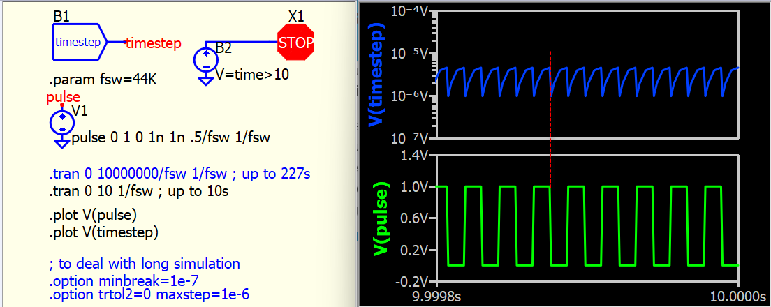
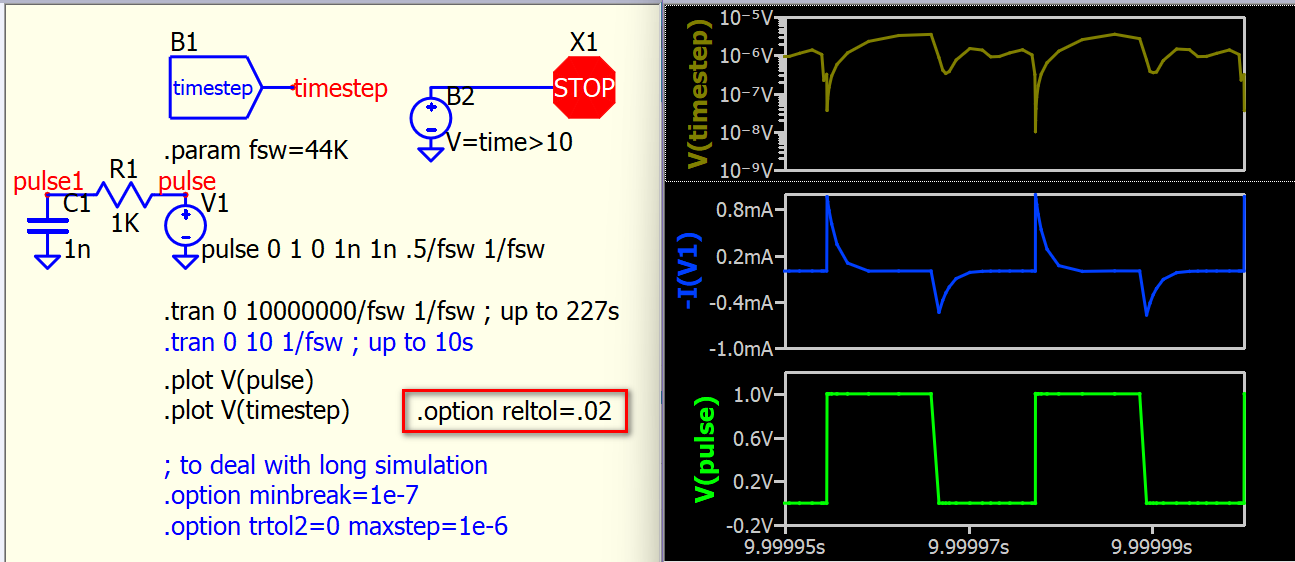
This is an example with a 44kHz pulse, simulating up to 10s. We can observe that its timestep only dramatically drops after the output changes and not before. Therefore, a deterministic source is expected to perform similarly to your algorithm.
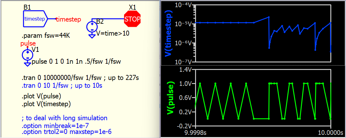
However, if simulated up to 227s, everything seems to be messed up! What we can observe in the timestep is that it may not reduce its timestep after a change event, or we can say that its timestep prediction is failing.
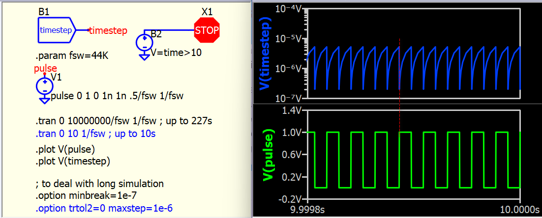
In the .option settings, there is a parameter called minbreak, which is automatically computed by default. I believe this parameter is similar to inst->ttol when compared to your C-Block Basics #5.
Now, if a minbreak is forced, the behavior will revert to that of C-Block Basics #5. Actually, my recommendation for the long run also includes setting trtol2=0 and maxstep=<value>. (I don’t suggest leaving maxstep to automatically calculate in the long run, this just like open up ceiling of timestep)
I fully agree that the timestep is a dark magic. Whenever I encounter a weird situation, my first step is to add a B-source with a V=time-state(1,time) function to study the timestep. In the C-block, we customize timestep control parameters, and therefore, it can behave as we want. I think in Qspice, the simulation setup can vary significantly case by case, and having a general algorithm to deal with all kinds of possible setups may not be that easy. Therefore, this might be the reason to somehow accept that it may not behave as we would like. The following terms all affect timestep behavior :
@RDunn, I think this discussion helped me understand more about the concerns regarding timestep. I didn’t differentiate between deterministic and non-deterministic cases in our past discussions. When I first received help from Mike, provided me with a code example for processing with an external clock, it was a typical Trunc() setup. After understanding how it works, implementing timestep control with Trunc() became obvious and easy. In simulations, I’m not too concerned about efficiency as long as my circuit can complete its simulation within a reasonable time. However, both @physicboy and you focus on code simplicity and simulation efficiency, working more in situations with deterministic timing control. So, after understanding this, I would say I fully agree with how timestep should be controlled in deterministic events. The C-Block Basics #5 example demonstrates code and simulation efficiency. Except for someone as lazy as me, who might just consider using the typical Trunc() for everything.
@Mike2, basically, you can just read the first two posts and ignore the following discussions. @RDunn gave a better answer to your question. I took this chance to document the timestep discussion with @RDunn as a follow up debate so that anyone needing deeper research with more information has something to read. After using Qspice for almost two years, and we still discussing timesteps, one can anticipate how challenging this topic can be.
Note: The “No. Points” is from the *.qraw files. Also, I’m treating the number of sample points as a surrogate for computational efficiency. For a C-Block using Trunc(), there would be extra unused computations which would increase the number of evaluations but not the number of simulation points in the file.
Then I added a 1pF cap across the clock generator without the various settings:
Kelvin’s, 1pF cap, no .option’s: No. Points: 10,319,727
Adding the cap appears to work about the same as adding all of the settings and half as fast as the minbreak setting alone. Was minbreak enough to get accurate results?
Then I compared to the C-Block #5 stuff. A couple of notes:
The code attempts to trigger an internal state transition exactly on the desired timepoint. The ttol parameter sets the minimum rising/falling edge time. (I should have called it something else to avoid confusion with the Trunc() TTOL parameter which is quite different.) More precisely, it sets the maximum time between a trigger point and the time when QSpice will sample the component’s next output port state(s).
The ttol parameter does, of course, reset QSpice’s step increment when edges are triggered so it shouldn’t be smaller than really required.
Also, the freqHz parameter isn’t technically correct – it’s actually the number of rising/falling edges/second so I’ve doubled the freqHz to 88KHz in the attached example to match your example. (I should make that more clear in the documenation or update the code.)
Anyway, some comparisons (again, highly sensitive to the ttol/rise/fall-time parameter):
Seems much better computationally but I’m probably missing something…
What conclusions can we draw?
My first thought is that we are playing with “toy examples.” A more complete circuit would typically contain other circuit elements and QSpice would sample differently (as demonstrated by simply adding that cap across the clock).
My second thought is that simulations are imperfect for simple analog circuits. QSpice’s addition of mixed analog/digital support adds another level of potential simulation imperfection. Maybe we should temper our expectations.
At best, I think it all depends on the specific use case how fast we want the simulation to run, and how accurate we need it to be.
Maybe you can do some comparisons of various parameters in your example vs simply adding a cap. If adding a cap is sufficient to ensure that the clock doesn’t go berserk without being significantly more computationally expensive, perhaps we could recommend that?
Finally, I hope that we will not still be discussing this in yet another two years, Kelvin!
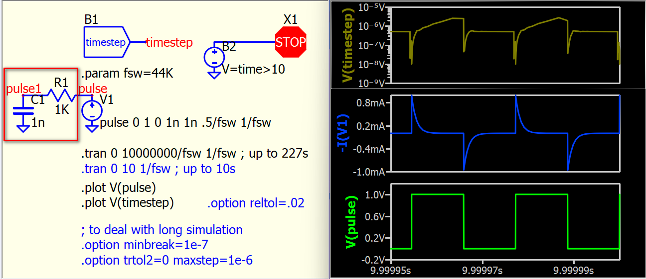
It may be easier to use a resistor and capacitor network to explain. With a capacitor added, SPICE requires calculating the current of the capacitor using the formula Ic = C * dVc / dt. Therefore, at the pulse edge, SPICE needs to calculate capacitor current and this involves numerical process. Essentially, the timestep must be reduced to achieve a convergent result in the calculation. But the timestep is more of a passive rather than an active choice during iteration. For example, if reltol (relative tolerance) is modified, the timestep also changes. A higher reltol allows a higher tolerance in the calculated results, resulting in a looser timestep.
Adding a capacitor: Forces the schematic into an actual circuit to be resolved, and the timestep is passively determined during the iterative process, where it can be small enough to converge to the allowed tolerance.
Using .option timestep-related parameters: Actively manipulates the timestep by forcing the deterministic source (Pulse source in this case) on what to do at its breakpoints.
In actual circuit simulation, both passive and active processes are involved, as it is not quite common for a circuit to have a source without a circuit to follow. Your audio wav conversion block is an exception, as someone may use it to run a very long simulation (audio signal simulation), but your external clock is only fed into a C-block input. In that case, I think it’s better to remove the external clock and implement it with your CBlock #5 algorithm. Deterministic case is better with deterministic timestep control, this is what I learn from our discussion so far.