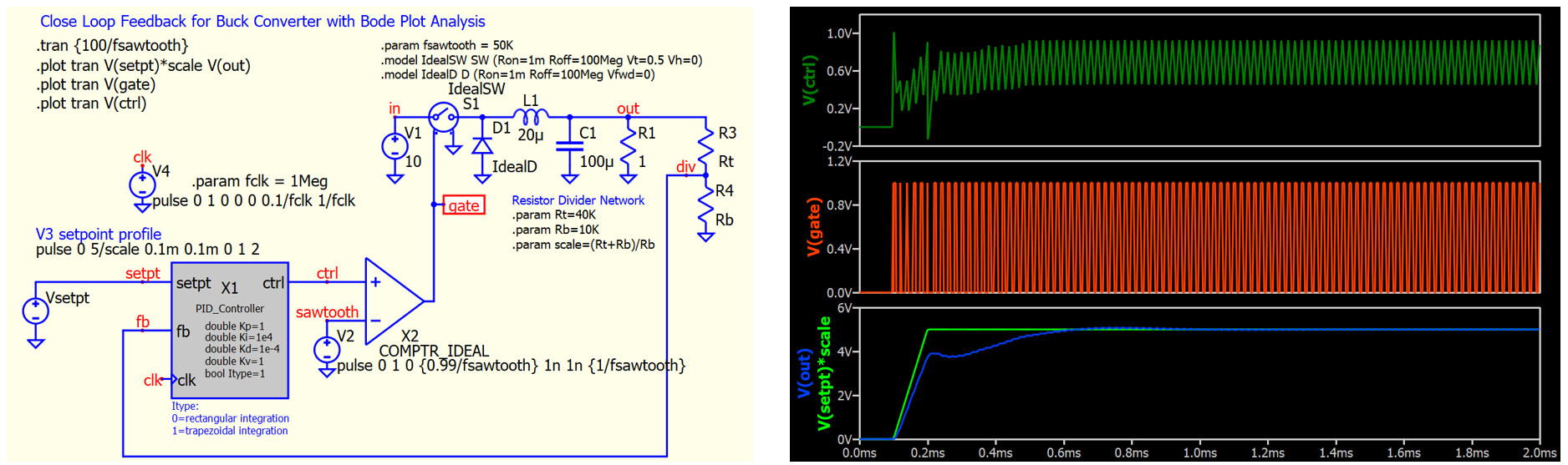
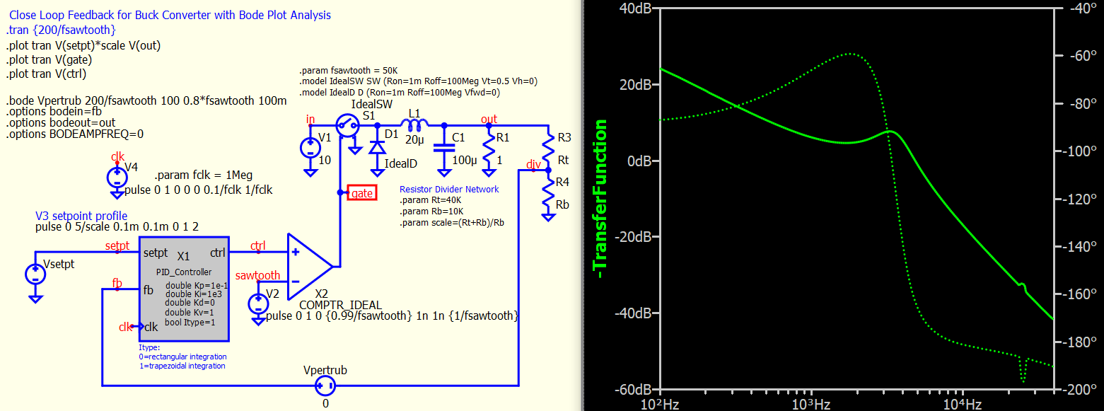
RDunn (@RDunn) and I worked together to create a C++ PID controller and would like to share to Qspice community. Symbol, C++ Code, Schematic example and explanation document can be download from RDunn’s Github in this link - github.com/robdunn4/QSpice
The operation principle, formula to implement integral and derivative and verification of code can be found in User Guide - Qspice C++ Discrete PID Controller Implementation.pdf.
Our purpose is to provide a startup kit for anyone who would like to include a digital PID in your Qspice simulation. You can modify the C++ code based on your application and we are welcome for feedback.
This collaborative effort wouldn’t have been possible without the help of RDunn in converting our idea into C++. This work is also based on a demo code from Qspice author Mike Engelhardt.
switch mode can’t simulation ac signal successful,that is very important for digital resonant converter design. S-domain mode is OK ! I hope it will come true soon.
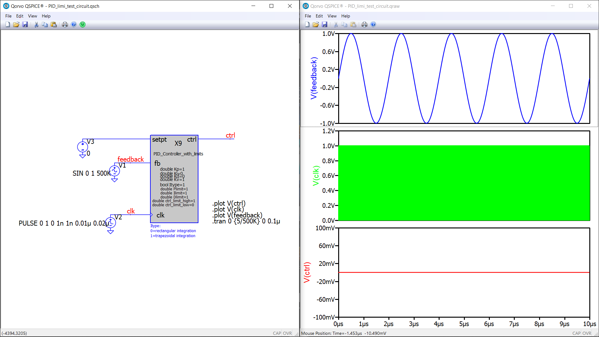
I’ve tried to add limits for each error (Proportional error, Integral Error and Derivative error + the ctrl signal), however my attempts were unsuccesfull.
My apprach was based on adding additional attributes to existing PID controller symbol and later adding them to .cpp file. However this doesn’t seem to do the trick. .dll can be generated just fine, controller starts (prints message about interation method etc), however output (ctrl) is always 0.
What is even stranger is that after removing all PID code (and leaving just the main loop with rising slope clock trigger) and forcing the ctrl output to a constant value (different than 0) doesn’t work as well. It’s almost as if connection between the symbol and source .cpp (and .dll) is somehow broken. Attaching test circuit and modifield .cpp codes (full implementation and one which should output constant ctrl signal), symbol file.
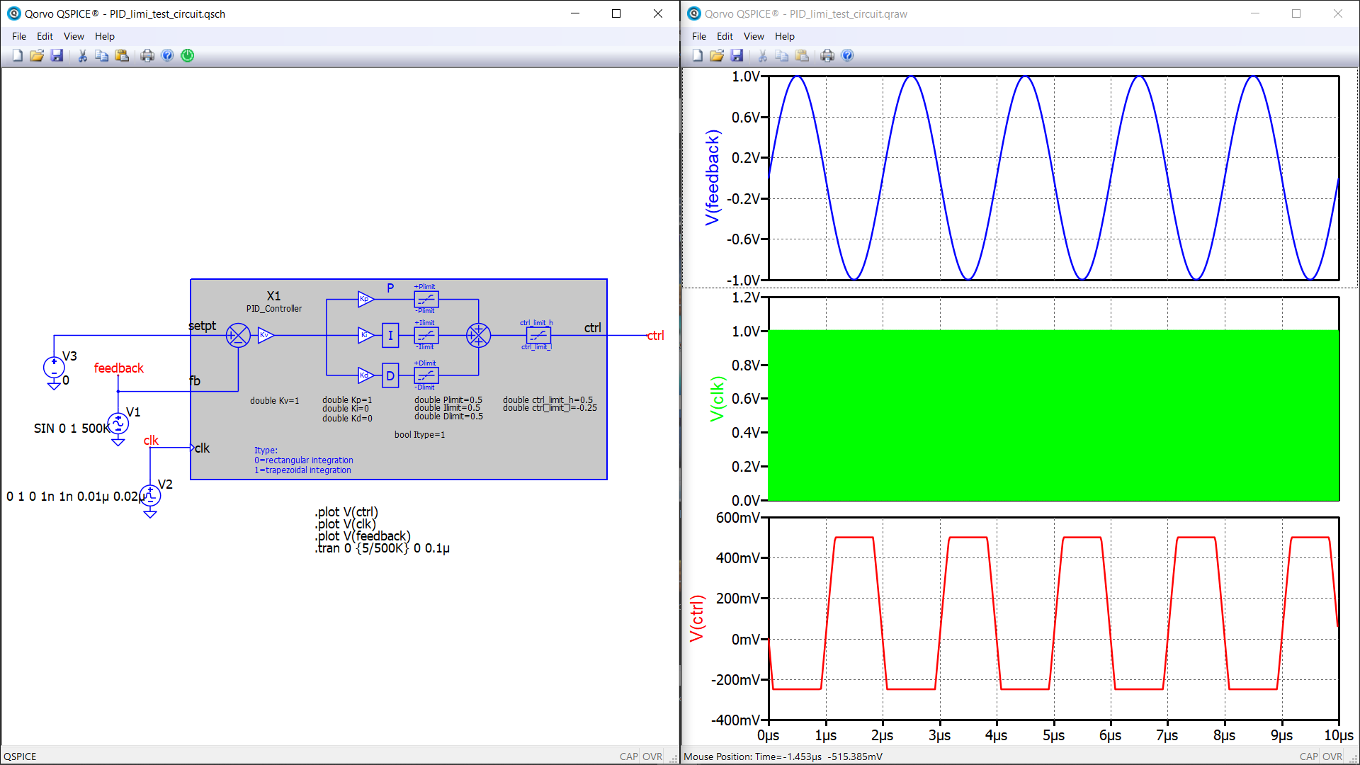
Edit2:
Here is the fixed version. I had to change the way how ctrl was computed. Instead of computing individual errors and multiplying them by their respective K multipliers in final PID formula they now being computed on the spot and just added together in PID formula. This forced me to devide I and D error by Ki and Kd respectively for storing n-1 errors. Don’t worry - code is immune to Ki or Kd being 0.
Please rename pid_controller.qsym to pid_controller_limits.qsym before testing. Also please rename the 1st atribute of the symbol to PID_Controller_limits before use.