Today’s featured design comes from Sandaru Imesh, an electrical engineering undergraduate at the University of Moratuwa in Sri Lanka.
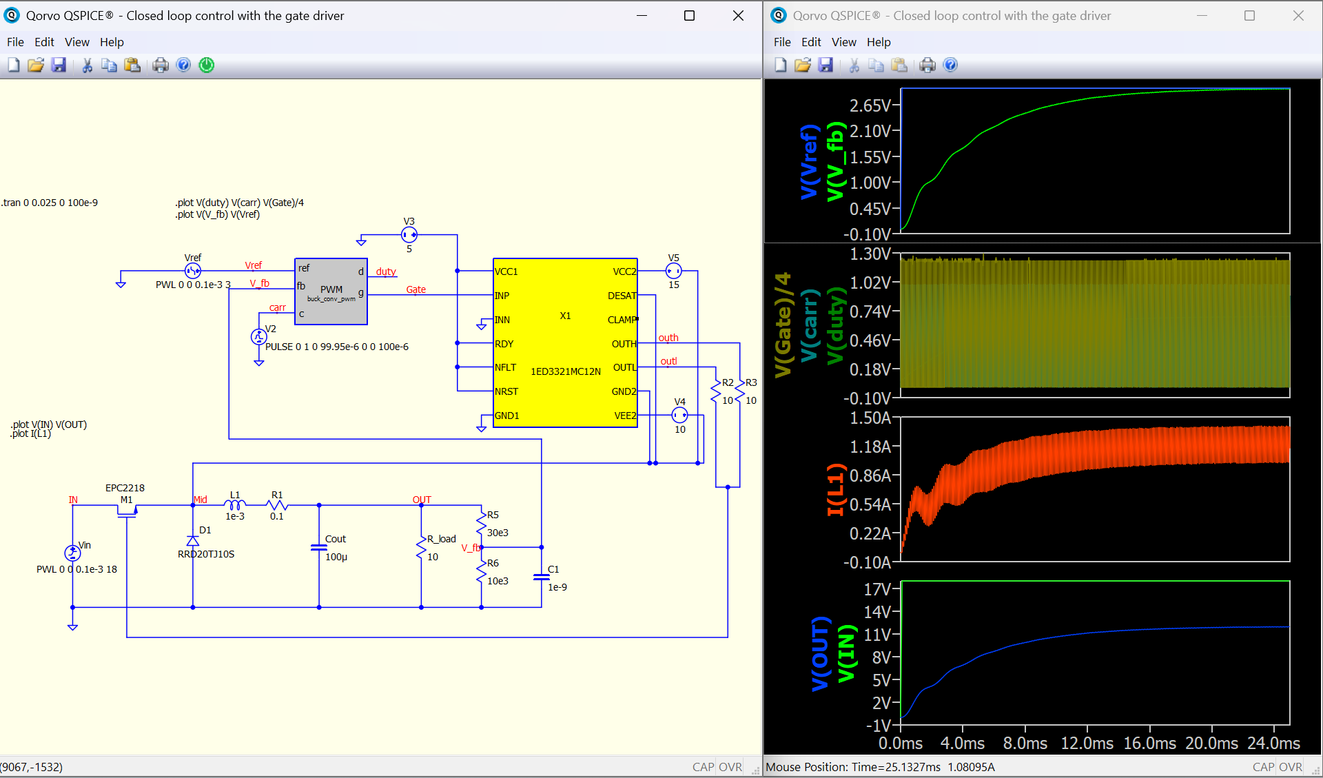
This project demonstrates a digitally controlled buck converter where the traditional analog feedback loop has been replaced with a discrete-time PI controller written in C++. Along the way, Sandaru tackled real-world simulation challenges including variable time-step behavior, integral windup, startup transients, and maintaining continuous conduction mode (CCM).
The result is a controller that automatically adjusts duty cycle to maintain a regulated 12 V output even as the input voltage changes—a great example of using QSPICE to develop and validate digital control algorithms alongside power electronics.
Please send any submissions to me at tim.mccune@qorvo.com (Schematic Capture Post #090)
buck_conv_pwm.cpp (1.3 KB)
Closed loop control with the gate driver.qsch (31.8 KB)