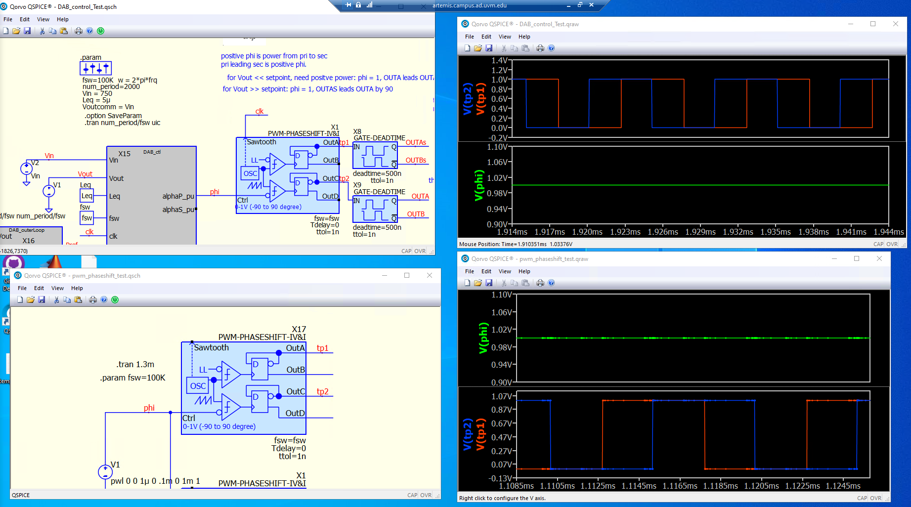
@KSKelvin This is hard-to-reproduce, but hopefully this captures my troubleshooting. The image shows different relationships between tp1 and tp2 when phi is 1 in both cases. I can’t figure out why they are different. Also, I think I’ve experienced the PWM-PHASESHIFT block to be “unreliable”. Yesterday I’m pretty sure tp1 and tp2 changed characteristic when I: (1) was confused (2) deleted block and saved (3) closed Qspice (4) reopened QSpice (5) replaced block (6) ran sim and it worked as intended (7) today it switch characteristic like this again.
The image is my best proof, but the sims I am uploading produced those curves, so hopefully this can be reproduced.
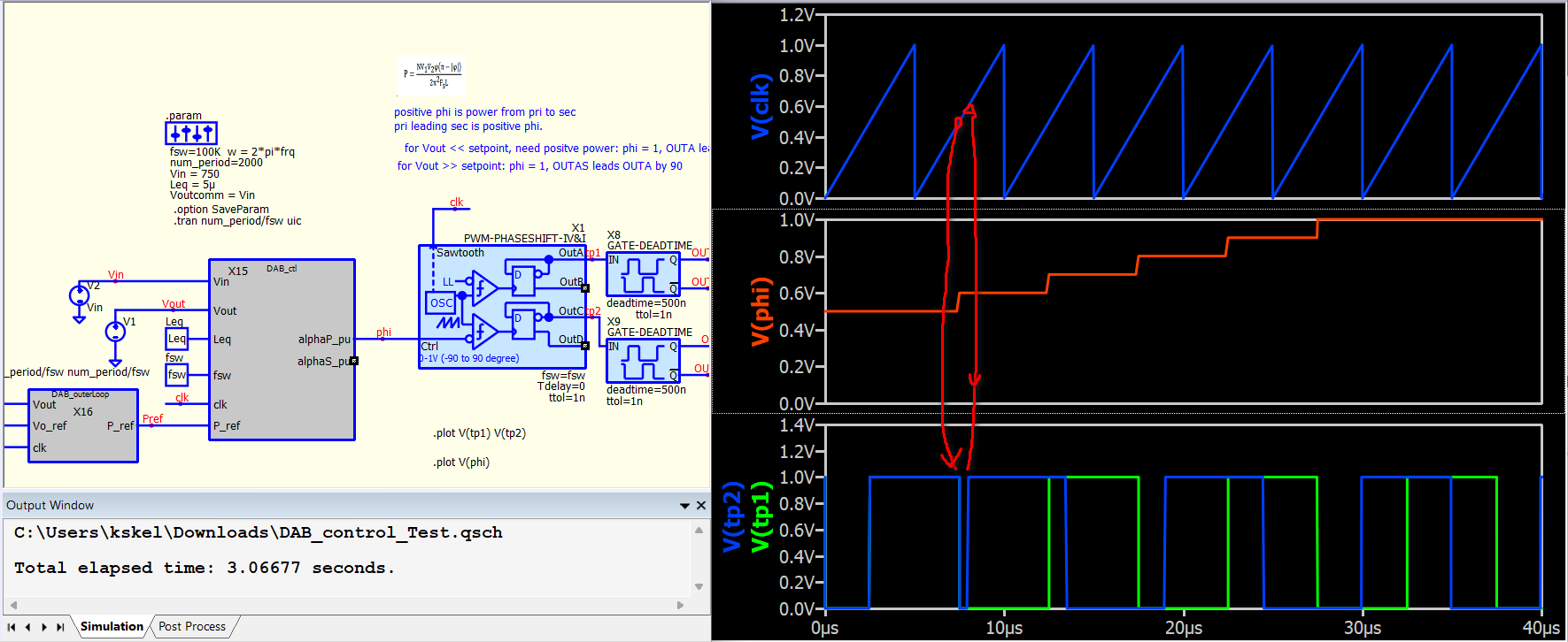
Well… I didn’t consider that phi is subject to discrete changes at a rate up to the switching frequency. I believe this could disrupt the comparator, causing the D flip-flop to potentially receive multiple clock signals and consequently completely flip its phase. I am not quite sure if this analog block is suitable in a system that with phi changed aggressively and not sync to the sawtooth.
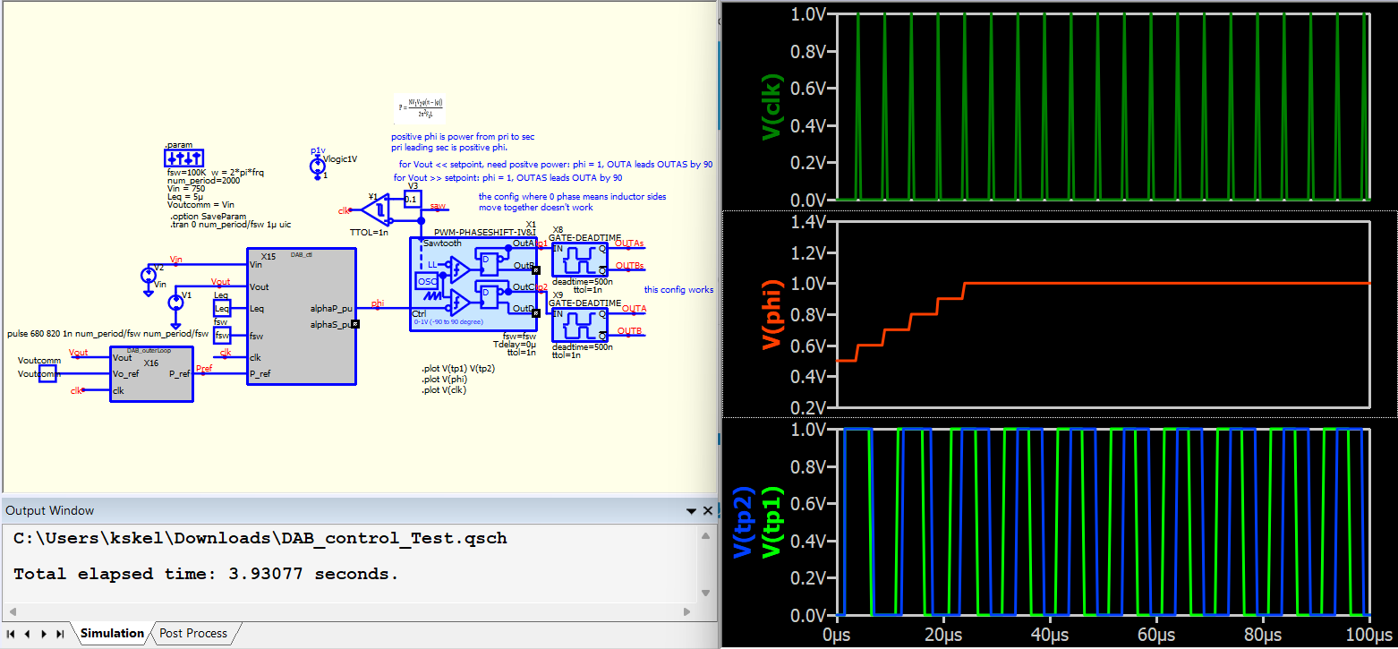
Do you think sync with the clock can resolve this issue?
I just realized that your initial circuit also syncs, but it syncs at 0.5V of the sawtooth. However, the sync should occur at the falling edge of the sawtooth, and phi has to maintain the same value in each sawtooth.
I have schematic attached in previous post.
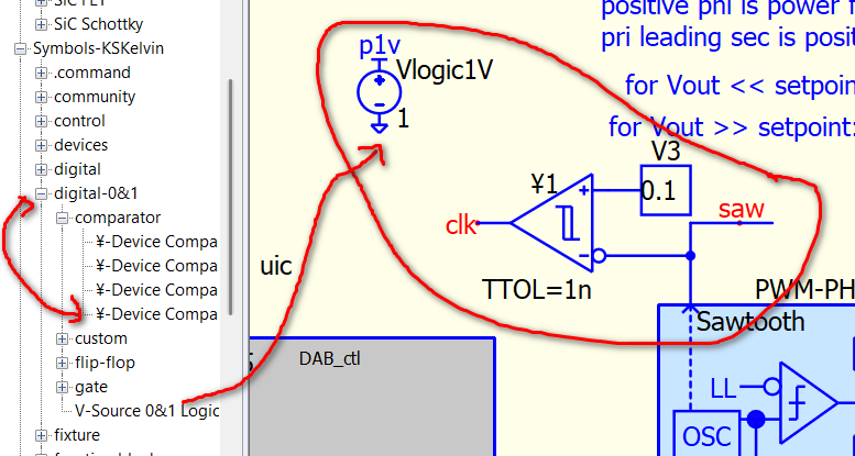
I have a digital-0&1 library for quick logic block placement if only 0&1 logic is required. It just speed up my schematic drawing as I don’t have to draw Vdd, Vss pin for every logic device.
If this solution proves stable in your test, I will modify my symbol by adding the clock out feature. Currently, it only outputs a sawtooth waveform. Please let me know if you believe this is the right direction.
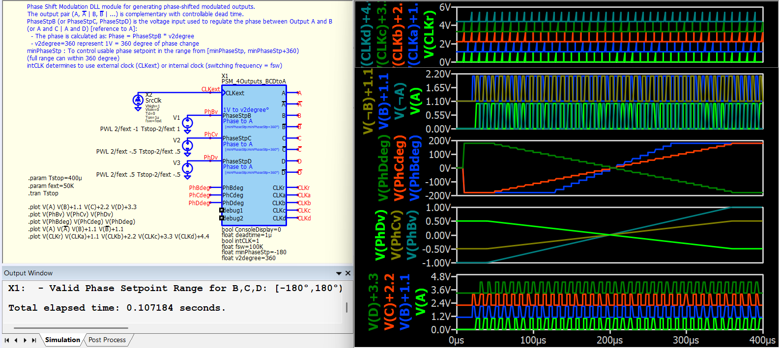
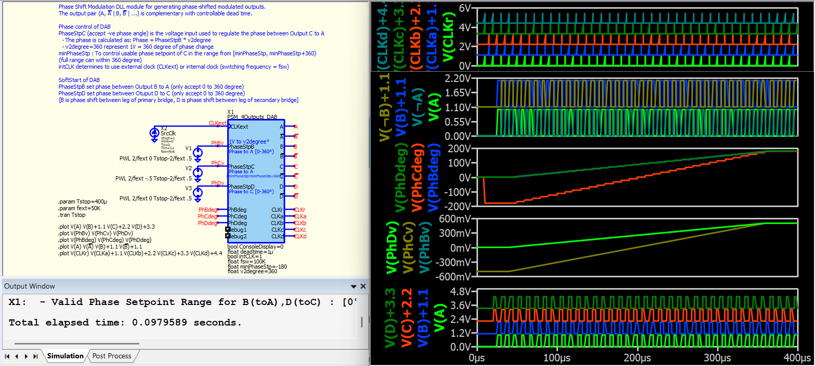
I have just uploaded the DLL phase shift modulation project, which I developed to fulfill a private request from a member few months ago. There are two blocksets: one with a reference output and three individually controlled phase shift outputs, and another focused on dual active bridge phase shift control. These blocks support an offset angle within their 360-degree range of phase shift. For example, setting minPhaseStp=0 provides a range of 0-360 degrees, while setting minPhaseStp=-180 provides a range of -180 to +180 degrees.
Thanks, I’m trying to evaluate now.
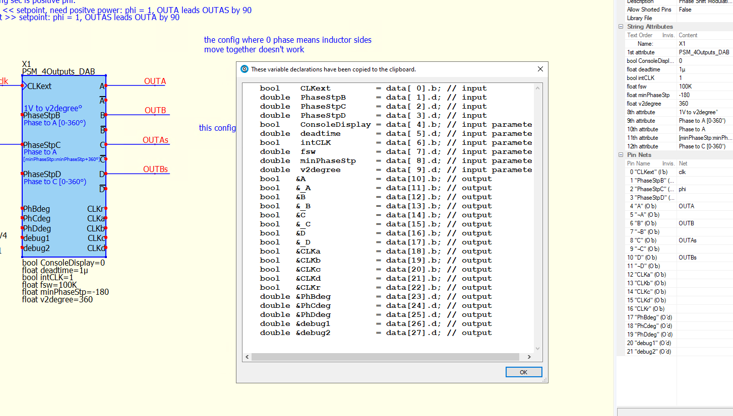
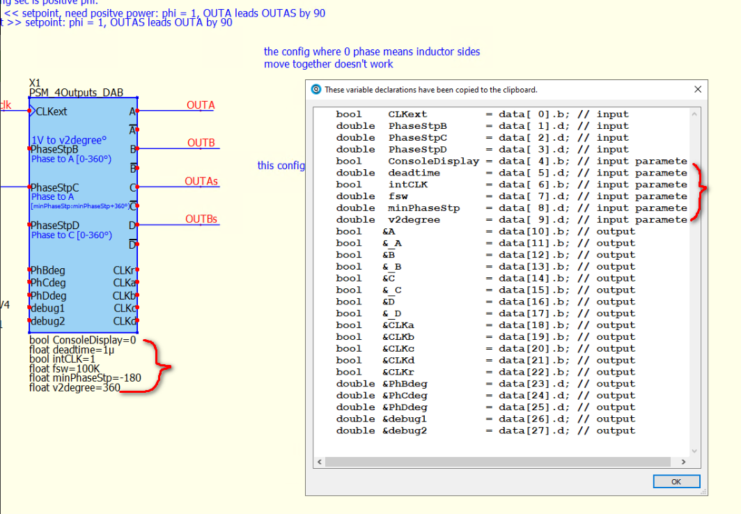
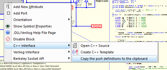
By the way, where is documented how the String Attributes of a DLL become input ports? I don’t see this in your Oslash documentation. (Right clicking to copy port definitions shows 27 ports, but symbol properties show 21 ports)
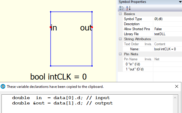
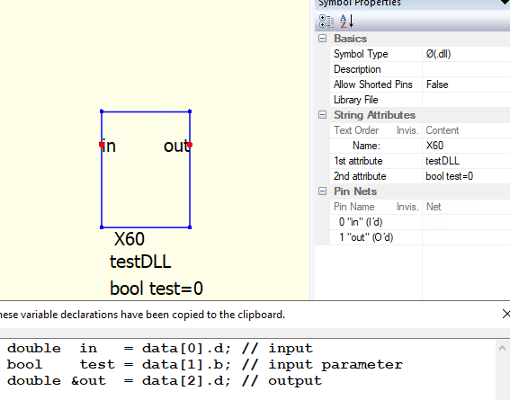
But how did you change the left column of String Attribute to say bool intCLK ? I can add an attribute, but it only lets me change the right “Content” column. And then I don’t see it in in the data array, or in the port definitions upon right click. I can ask in a new thread if that makes more sense.
You type the entire bool intCLK=1 (must have = with assigned value) as an instance parameter. Port declares its data type through the right-click menu, whereas a parameter declares its data type by directly typing it as instance parameter, similar to declaring a variable in C code.
I tried that, it just puts “bool intCLK” in the right column , and does not add this to data array like the other pins.
Do you have to edit the data array in C++ manually?
Maybe the Oslash parameters have to be added from symbol editor. I am attempting to do so from schematic editor.
@Hans_Goldenrod
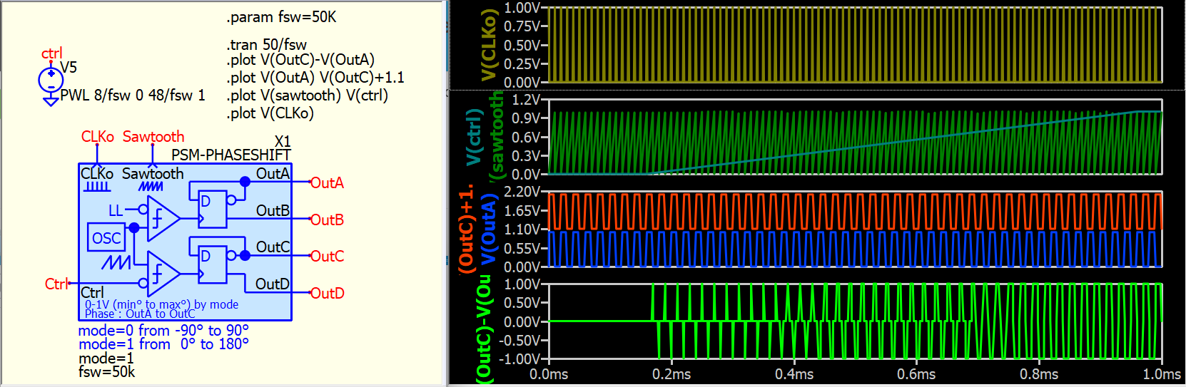
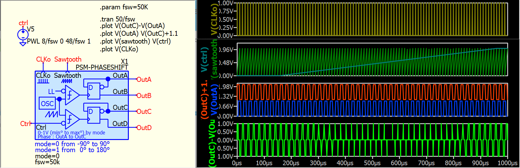
I have made several changes to my behavioral phase-shift modulation symbols and renamed them from PWM-PhaseShfit to PSM-PhaseShift. Please consider updating it from my library.
I have consolidated the -90 to +90 and 0 to 180 ranges into a single symbol, and the mode can now be switched by selecting 0 or 1. Here is an example for your reference. I hope I got it right this time, and the issue of multiple triggering of the D-flop within a clock period should be resolved in this version.
thanks so much. I’ll let you know when I can try it out. It might not be today. I’ll also close the loop on the DLL block parameters (I had used = sign already). I’ll look at RDunn’s documentation to see if he talks about this. By the way, I did get your DLL phaseshift block to work for my application.
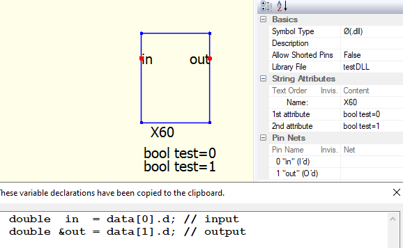
And then adding a parameter. But the “bool intCLK=0” just stays in the right “content” column, whereas Kelvin’s show the type in the left column, and the value in the right. I realized that the 1st attribute needs to be a Name like “X60”. So then I added a second attribute and it worked:
Question: Why doesn’t the type “bool” show up in the left column, like Kelvin’s?
I then tried to use the Library File again, and added a second attribute (but still have Name field), and it stopped working: