Hello
I am trying to simulate a buck converter with a sinusoidal perturbation on the duty cycle. My idea is to test the ".meas fra " statement to obtain the bode plot of the duty-cycle-to-output voltage transfer function.
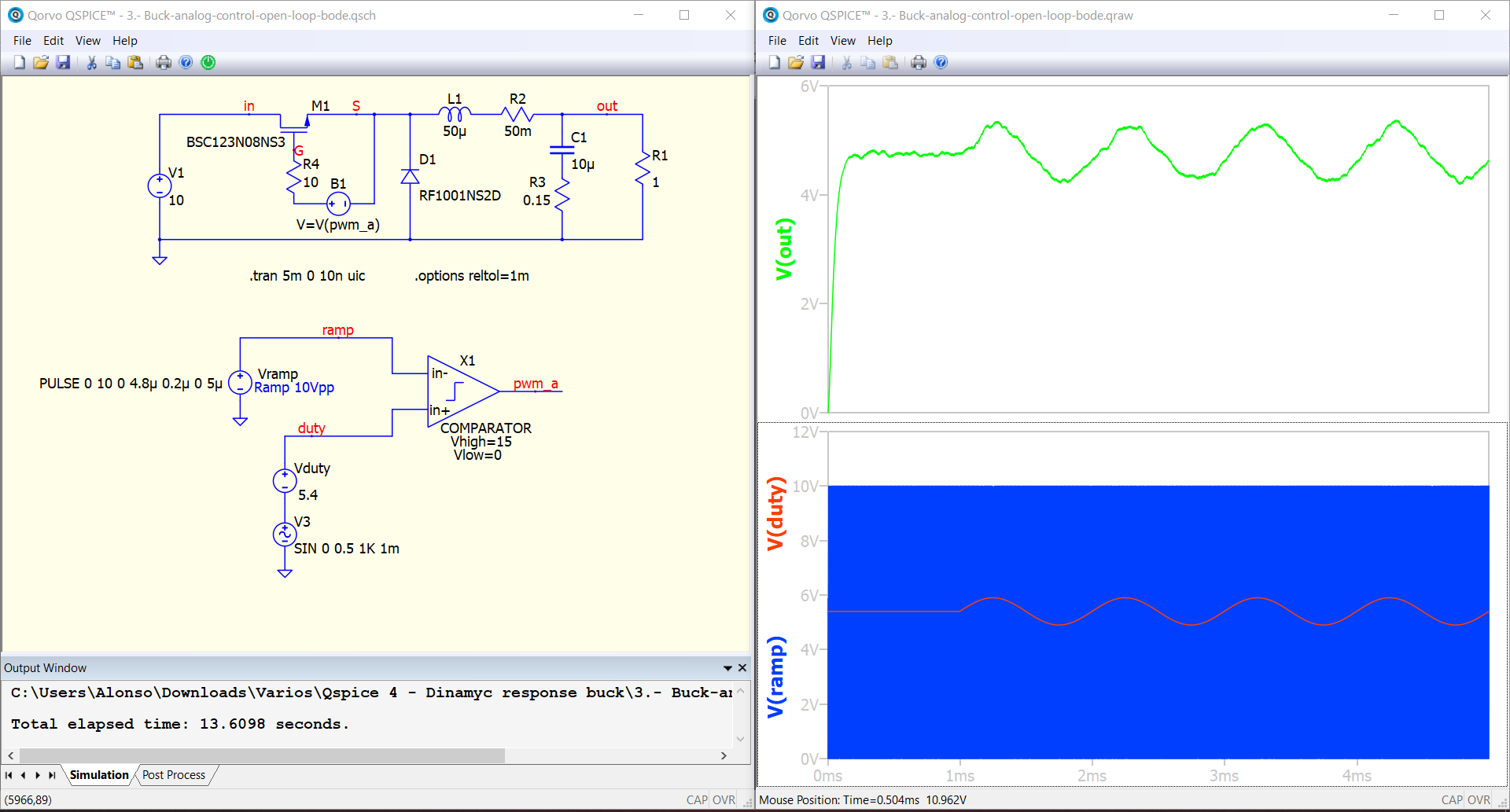
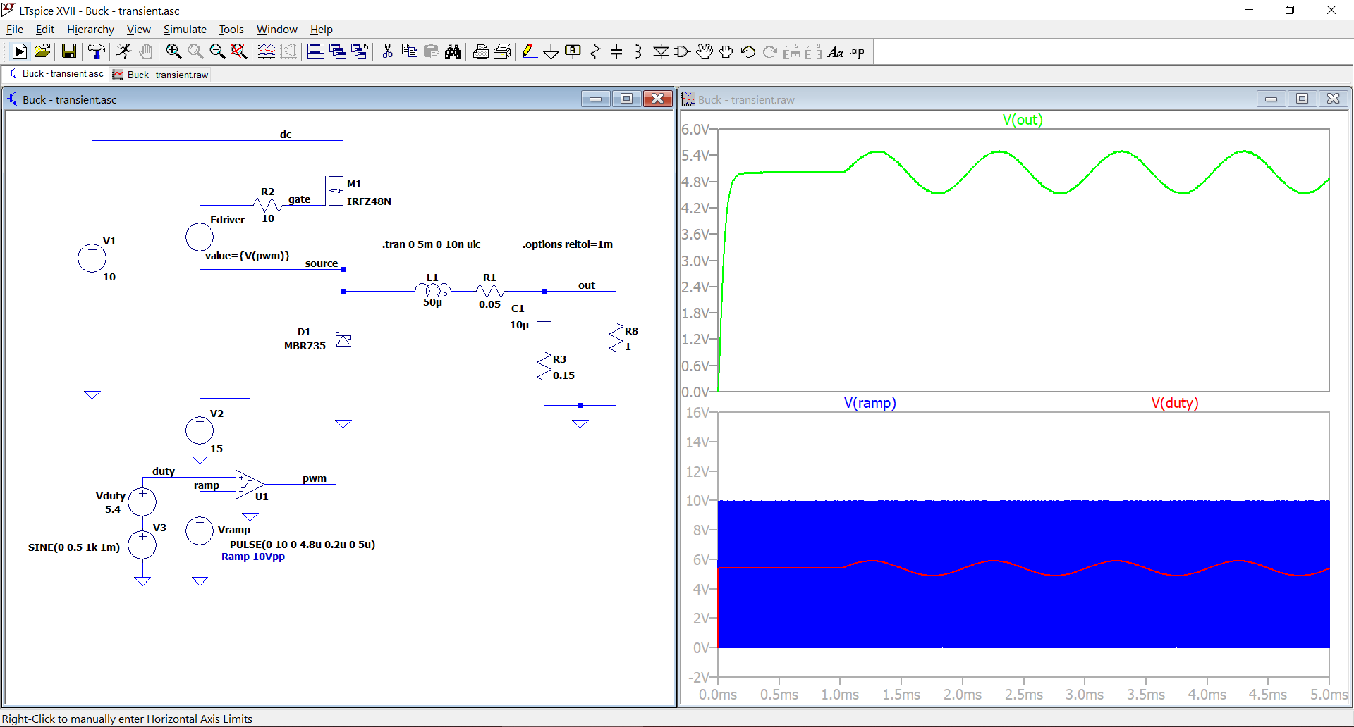
However, the simulation results in Qspice are very bad. I have simulated the same converter in LTspice in the same conditions and everything is fine.
In both simulations the comparators are defined in the same way:
.subckt comparator in+ in- out
E1 out 0 Value = {if(V(in+, in-)>0, {Vhigh}, {Vlow})}
Rin+ in+ 0 10Meg
Rin- in- 0 10Meg
.ends comparator
But from what I see, simulation results in QSPICE are nearly the same as in LTspice. Then why do You said that the simulation results are fine in LTspice, but in QSPICE the simulation results are bad?
Or do You refer that simulation results in QSPICE are bad looking for example at Vout and seeing that on the waveform is superimposed some harmonics?
Try the same .tran command in QSPICE as IT is written in LTspice. Then only difference are in mosfet and diode…
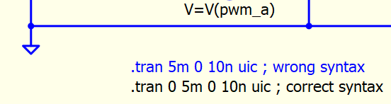
@marcos.uniovi a quick answer, wrong syntax in .tran if you want to use maxstep
In HELP, two type of .tran syntax. When you need Traditional Berkeley syntax, the first value is IGNORED. If you refer to LTspice, it automatically do it for you. It is a common mistake when we switch from LTspice to Qspice.
You can also set maxstep with this method
In general, using TTOL device (includes TTOL in .DLL C++ block) can help to reduce simulation time as compare using maxstep, and in certain situation, the improvement is huge (but not in your case, only 20% reduction of simulation time).
Here is a comparison with maxstep and ttol approach. I modified your comparator library path to MyLibrary.txt, so that I can run your simulation only copying everything into a same folder, which is better for sharing purpose. As forum not support .lib to upload, I use MyLibrary.txt for everything.
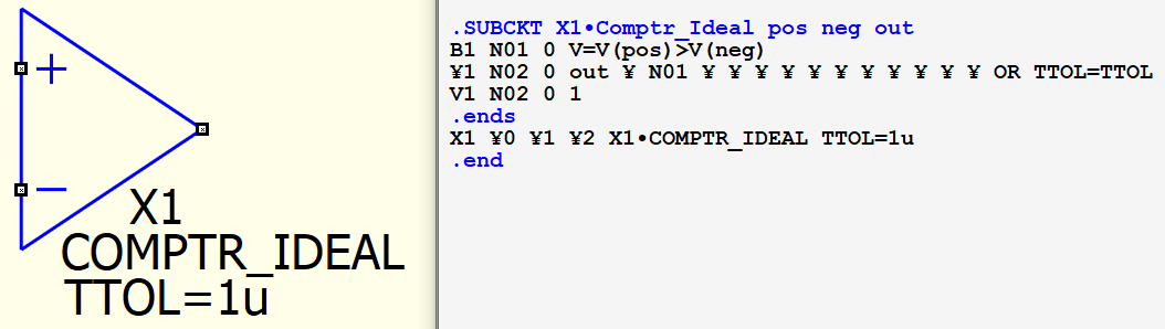
Finally, I created embedded .subckt symbol (no need to carry library file) likes ideal comparator with TTOL, ideal opamp with same .subckt as LTspice opamp.sub etc… this link include these symbols and a pdf explanation document.
Yes, the problem was that the waveforms were very poor compared with LTspice. I see now the the mistake was in the .tran statement. I need to add a 0 at the beginning. Sorry for the oversight.
Thanks!
The only disadvantage that I see in using an embedded symbol is that everything is packaged in one line. It is difficult to see how the component is defined and maybe make some changes if necessary. Or maybe there is some way to see the model in a more convenient way that I do not know of?
I agree that embedded symbol has its advantage and disadvantage, it is more suitable for relatively standard function symbol where change may not commonly required. The major disadvantage is that embedded symbol uses one line syntax which is not convenience to read. I just wrote a matlab which can convert embedded symbol into netlist format. This matlab can open a .qsym and re-format one line .subckt syntax into a netlist.
To modify an embedded symbol, I think after export it into a netlist for modification, copy that netlist and paste into Qspice for autogenerated symbol, the corresponding one line syntax can be created, the rest is just to copy this one line back to original symbol (to prevent redraw the symbol, but just modify the Library File content).
Oh… I just remember an easy way to get one line .subckt syntax into a netlist in Qspice.
Just drag the symbol into a schematic, View > Netlist, and you can get netlist of embedded subckt symbol, only subckt name X1• is added and you have to manually remove it.