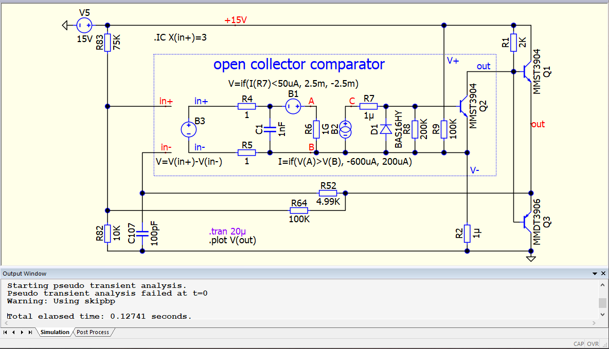
There seems to be a persisting bug crashing the simulation and reporting a misleading “Warning: Singular matrix. Check node B” error messages. I had to look far and deep in this forum for similar reports. While it is not a new issue, seems that in fact is something much more fundamental, something really wrong with the way QSPICE builds a netlist.
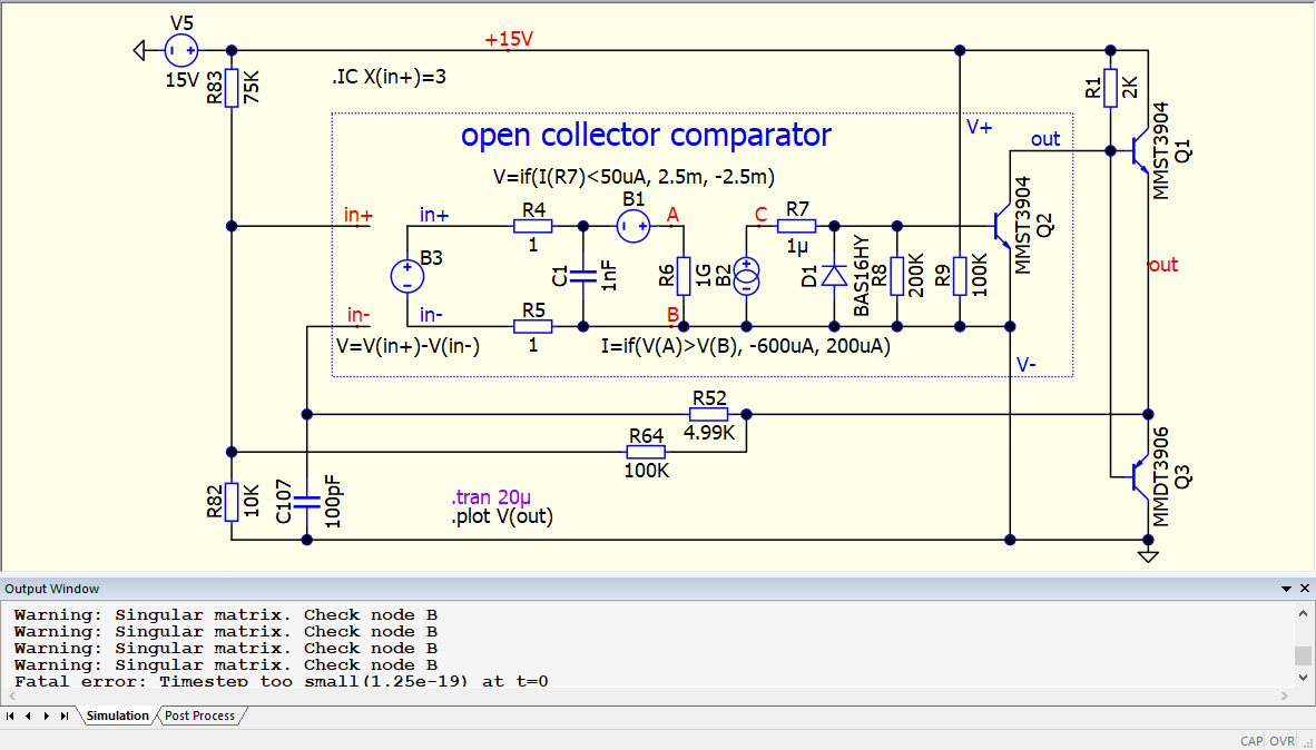
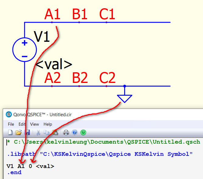
I added here a test demo, showing this issue. The way I put together this schematic works now. But, if we delete and replace the helper resistor (R2 with the value 1µ) with a direct wire connection to GND, the simulation will crash. Since this is an absolutely benign resistor with no obvious function, I have to assume I just stumble on the root cause of these abnormal crashes.
Is there somebody that already understood the issue here, maybe I am missing something? I burned out quite a bit of time to understand this problem, and for now I am totally lost.
The primary issue with your schematics is that node 0 which is ground overrides node B. Best way is to do same thing you have done to add resistor to split node to node B and node 0.
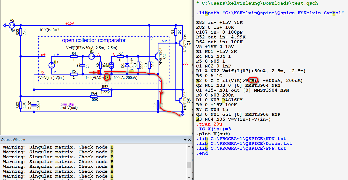
what @ivan1 is trying to convey is that when you use a short, you replaced node “B” with node “0”, and in this schematic, node “B” no longer exists. It is crucial to exercise caution when assigning different node names to the same node, as only one name will be taken into account during netlist generation. The node “0” is automatically assigned as the ground (GND).
In this particular case, you cannot use a short, but you can utilize a 0V voltage source if you prefer not to use a 1u resistor.
By the way, this issue is a warning and not a crash. I had initially assumed that you were referring to a schematic that could cause Qspice to crash.
By the way, since the B2 formula references node B in its formula, when you short node B to GND, B is replaced by 0. This is why your formula refers to a non-exist node and triggers a warning.
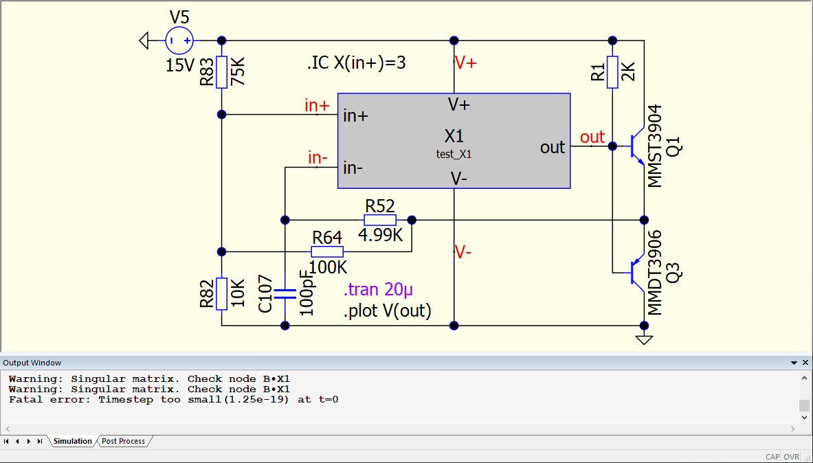
@KSKelvin The issue is shown in a basic application to make it easy to understand. The problem is more complex when you have multiple nested subcircuits in a complex schematic, from various manufacturers. In that case I would have to open all kind of models and add various helpers around. I would say is a bug, since standard models and subcircuits will always create this problem. You explanation clarifies why and how to work-around, thanks. Not even opening here the can of worms with encrypted models.
For example, when the subcircuit model is embedded is a library file it makes no difference how many helpers are placed around, inside and outside the model. I still get that error: Warning: Singular matrix. Check node B1•X2#BRANCH
Maybe I am missing some other details, but still smells like a bug.
I believe you have defined your sub-circuit incorrectly, resulting in this warning. Please upload both the parent and subckt .qsch files, and I will review them to determine the proper way to set up this configuration.
As an experienced Spice user for over 20 years, I would not classify this as a bug.
Spice workflow is that,
schamtic .qsch is convert into a netlist by QUX.exe (this GUI interface)
The netlist is run by simulator Qspice64.exe or Qspice80.exe when you press Run
The result (.qraw) is plot in waveform windows
Currently, it is a nature that how your schematic is convert into netlist. When multiple node name is defined for a node, it will only take one of its name. If without node name, it auto assign. But ground node always override everything with a node name 0.
@KSKelvin I appreciate your help, I think I understand where the issue is hiding. Unfortunately I cannot upload some stuff from work, besides basic simplified examples. I can fiddle around and patch it for now. But the issue will be there, and probably should be fixed sooner or later. Maybe I will be able to duplicate some of the models at home, if there is a need for a more elaborate example. As it is right now, there is no connection whatsoever between the symbol pins to GND, it is 100% hidden behind the resistor. There are no more “unified” net names. Thanks!
Edit: I uploaded here the SUBCKT MYCOMPX.txt (902 Bytes)
That’s great to hear!
“View > Netlist” is always your best friend when troubleshooting. The schematic is merely a GUI that aids in converting a visual schematic into a netlist. Thus, what you encountered is actually how this GUI handles the conversion process from a schematic to a netlist. Qspice and LTspice (and possibly other) do not issue a warning when multiple node names are defined for the same node. It sometime can be confusing for user who are not familiar with netlist yet.
@KSKelvin just a side note, the circuit has no multiple net names defined for the same node. Adding that R11 resistor from V- to GND is completely, fully isolating the names. And yet, the “singular matrix” is still claimed in the output.
@daddyzaur Your Netlist shows pin 4 as the ‘Negative Power Supply’ which is the ‘B’ node. When this pin is tied directly to ground - it is renamed node ‘0’ that then causes the problem. It should be understood that a V- input can not be tied directly to ground - but if we think it should be able to - then that is the bug. Is that correct? The problem I see is that R2 when 1u should correct the node naming issue. So is the real bug that there needs to be a resistor (or component) with a value above some specific level to be considered or treated as a new node name?
This is a problem regarding how the schematic GUI should respond to multiple names defined for the same node. Qspice’s QUX.exe generates a netlist from the schematic. Based on my observation, the current behavior is as follows:
If a node connects to GND, GND will always override and name the node as 0
If multiple names are defined for the same node, the earliest one is used
When a small resistor or a 0V voltage source is added between node names, it effectively splits a single node into two and assigns different names to these two nodes. The problem encountered in @daddyzaur’s schematic is that the original node name “B” is also defined to be used by a B-source formula, when the node name “B” overrided by 0, node “B” is removed from the netlist but B-source equation still looking for V(B). As a result, a warning appears, prompting the user to check for node “B” as it is no longer present in the schematic.
If this behavior should be classified as a bug, it seems the most reasonable action would be for the GUI to warn the user when multiple names are defined for the same node during netlist generation. However, someone in the community would need to email and discuss this matter with Mike.
It’s important to note that this issue rarely occurred in the past. However, with Qspice offering the “Stuff with jumper” feature, unintentional merging of two node names can occur.
@KSKelvin Ok, I’m with you. I misunderstood - I thought he was saying that even with a resistor of too small a value - like 1 uohm that he got the error. Yes, I commonly use resistors of low or High values - depending on the case - to solve these issues. If I need to add a ground to a portion of the circuit that doesn’t have a reference - then I use the high value resistor. BTW, I like the idea of also using a voltage source to split the nodes. Is there a benefit to do this vs using the small value resistor?
In theory, same node with same potential, and a 0V voltage source should provide the same potential when used to split the node. Additionally, I utilize a 0V voltage source for current measurement, particularly for sub-circuits. However, through observation, I have found that using a 0V voltage source for current monitoring is preferable over employing a small resistor. In extreme cases, a current monitor implemented with a small resistor can introduce unstable current readback, possibly relates to precision in math.
@KSKelvin I think it is not so bad to get distortions on the current waveform when looking at nanoamp resolutions. In a physical circuit you have to put in a some work to have a clean nanoamp level signal. Even though the noise is caused by different mechanisms in the physical and simulated circuit, you get noise either way, which is probably better than having a clean nA level signal. It’s even worse when spice simulates some perfect waveform in the femto amp range, good luck re-creating than in a circuit
This issue is unrelated to nanoamp resolution. Even when scaling up the input voltage to read currents up to 1A peak, I(Rcurrent) still yields unstable results that do not precisely match I(R2) or I(V1). In a given current loop, one would expect these values to be identical.
@KSKelvin I see what you are saying that there is not enough resolution somewhere in the numeric value used for the calculation. Maybe its the bad impedance match between 1u and 100Meg on the net between 1u and 100meg. I know the noise is not directly due to an impedance match but in the math if you have to “connect a port” of which one sides impedance is in the magnitude of 1e-6 and the other side is 100e6 I can imagine you might get poor results mathematically as you floating point operations have to adjust to the 1e6 range and your 1e-6 range gets lost in the noise.
Any way my original point was more about math vs reality, just like the circuit you have shown here, spice simulates it but are you going to implement a 100MW resistor? The spice simulation should have an easter egg animation where the resistor turns red then shows a nuclear mushroom cloud : )
I didn’t address the practical aspect. The observation was made in response to @KissAnalog’s question regarding the advantages of using a resistor to split a node compared to a 0V voltage source. Therefore, I would like to mention one of my observations from spice simulation when employing a resistor versus a 0V voltage source.