When running a simulation for a circuit with dual 24V DC voltage sources switched by PWL-controlled voltage sources (both PWL 1 0 1.2 5), I notice the voltage values generated by the plots for various nodes seem correct. I used this PWL to study the transient behaviour of the circuit in the seconds after power on.
However, when afterwards hovering the cursor over the various nodes in the schematic, I find the values displayed are only order of millivolts or even microvolts, rather than the values reflected correctly in the plots.
To give an idea, the values for 4 nodes in the schematic, are plotted as +3.7; -2.17; -3.5 and -17.6 Volts. These are the values after stabilizing, i.e. shown as horizontal lines between 3s and 12s. I ran command .tran 12.
The values from the exported node operating points file (as KSKelvin kindly explained in a different posting), for the exact same nodes, are respectively: -0.00124012; 2.85424e-07; -0.00208545 and -0.00187295 Volts.
The values listed in the exported file correspond to the ones showing by hovering on the nodes in the schematic, but have gone totally different from the values in the produced plot.
I am probably missing something important here…
And again: all my respect and compliments for Mike Engelhardt and KSKelvin !
Paul
The voltages seen when hovering the mouse are operating point, before time starts advancing. Not the final settling values. The big value of the operating point is that if you do a .AC analysis, you see the bias point of the circuit in addition to the freq domain data.
Would there be a possibility to include a parameter with .TRAN to show the voltages of the operating point at the moment the endtime specified with .TRAN has been reached ?
Or maybe more generally a parameter specifying the point of time at which to show the operating point voltages and currents of the nodes, when hovering over the circuit?
I don’t know how to perform a .AC analysis, when the circuit is basically powered by DC, after the delay specified. The idea being to visualize all values after they have stabilized (after the power-on transition) ?
Or could I maybe use the .AC analysis in a very specific way to obtain this ?
Most common analysis in spice are .op , .dc, .ac and .tran, which equivalent to what you normally learn in circuit theory course.
.op is dc operation point analysis, to calculate DC steady state voltage and current
.dc is dc sweep analysis, it likes .op but can change source voltage/current during analysis
.ac is ac analysis, same as in circuit theory using phasor for calculation. before .ac is run, it automatically runs .op for dc operation point and .ac is simulate on this dc condition
.tran is transient analysis, in default, a .op is run before .tran, and .tran is run based on this bias point condition at t=0s. User can skip .op by adding UIC in .tran directive
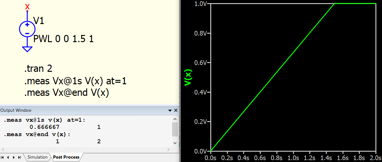
When hovering over the circuit in .tran, you are getting its .op analysis result. If you need to get Tstop data but without probing data from waveform viewer, what you can do is to use .meas directive to measure data at particular time, and its result is returned at Output Window. You can get more information of .meas from Qspice HELP. I cannot see a way you can visualize all value at Tstop for .tran. You have to write a program to process output data. But if only certain node is in interest, .meas is what can help.
Using .meas I can indeed output a list of text showing the voltage values for some selected nodes, but this is only a workaround.
In the Qspice Documentation I cannot find any time parameter for the .op analysis.
The .dc analysis is to sweep a dc value of a voltage/current source, which is not really the issue in my case.
Actually, it would be helpful to have a time parameter for .op in order to reflect all the voltage/current pairs, not at t=0s, but at t=Ns with N the time value in seconds, after the simulation was started.
This would be to show the various final values in the circuit, at the moment where the switch-on operation has stabilized and all transients have passed.
Using the .plot graphs, on the other hand, both transients and stabilized values are perfectly viewable, to show what happens at various nodes during the interval between t=0 and t=N
It would just be a nice added feature if the final values for t=N could all be reflected at the nodes in the circuit ?
.op is a single point DC analysis to calculate steady state response of a circuit, it is useful for non-switching circuit.
.dc is to allow sweep of voltage and current source to perform multiple .op opertion to give you the result.
.dc is equivalent to use a .step to change source voltage or current in .op
in electronic, for steady state or DC operation point or bias point, it calculate result of steady state, i.e. time to infinite. But the calculation never require time information as in steady state, because capacitors are fully charged act as open and inductors as short circuit. Based on that, calculation can elminate all time dependent elements and perform calculation. You normally learn this technique in circuit theory especially in calculating transistor bias condition. This technique is useful to get steady state result except for circuit with switching elements (e.g. switch, logic or dll block). For switching circuit, it normally require transient analysis to get result at steady state.
In short, .op .dc or .ac has no time information. In electronic, we learn how to solve circuit without going into solving differential equation, which means eliminating time in the formula.
In transient analysis, .op is performed before transient is run. This represent .tran firstly assume circuit is reached steady state and to start calculation. In real life, for example, you normally run power for audio amplifier to allow its reach steady state before apply audio signal. So, steady state result became t=0 starting condition. If you don’t want .op before .tran, you have option by adding UIC in .tran.
.op, .dc, .ac and .tran are four basic directive in any spice simulator and not unique to Qspice. You should able to get detail information from internet or textbook.
For node snapshot, it basically a post processing of .qraw datafile. In the forum, there are two projects to use programming software for post processing data and you can refer to this post. You can do whatever post processing currently Qspice waveform viewer cannot offer.
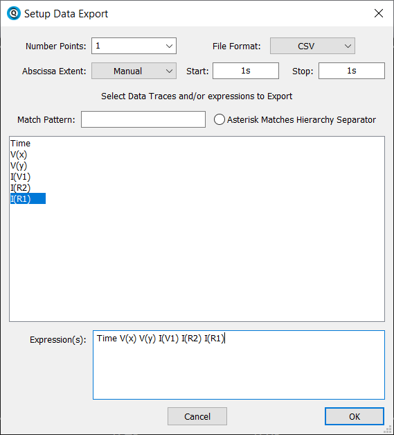
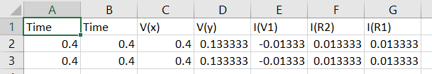
In waveform viewer, File > Export Data…
Set as following to export a CSV at time you need. But currently I have to manually click each node to add into export expression.
And what is the best approach in the case of switching circuits (for example, dc/dc converters, or any other switching circuits)? Because I have seen that when running .tran simulation in switching circuits, and in addition if that switching circuits has also some gate logics (i.e. and/or gates or RS flip flop) or some code, the simulation encountered problem when simulating the circuit…
I believe a lot of community members have experience to simulate complex converters in transient analysis. I agree simulate power electronics circuit is not easy, especially to close-loop the converter. My practice is to begin with ideal switches and behavioral diode, make sure open loop response is reasonable before closing the loop. Break down your circuit, simulate section by section and never to expect you can put every circuit components just according to a schematic or application notes and thing can work.
If you have difficulty in your simulation, open a topic and post your circuit file and question in this forum.
I had hard difficulty when simulating a asynchronous dc/dc converter in closed loop (so, a converter with all switches made with ideal switches, and not using any diode for switching elements).
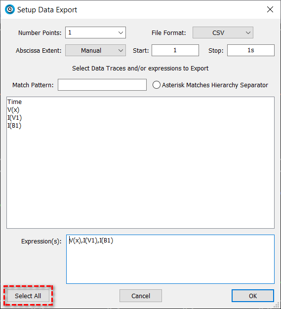
In Build Dec 7 2023, Mike implemented a button to select all traces. For .tran, Time in default always save as first row and not necessary to include in expression selection.