I’d like to try to model an opamp based on its datasheet. As an example I took TLV9062 from TI.
I’m facing several challenges:
The description of the model parameters is very brief and sometimes confusing (e.g. IOUT vs. ISRC/ISNK). I’d appreciate some more descriptive/explanatory manual how to work with these.
I’m not sure if and how to initiate parameters that are not explicitly mentioned in the datasheet
I created a schematic (attached) that should represent the test circuit as defined in the datasheet and it runs enormously long (3ms simulation took several minutes). What is wrong with it? OPAMP_model.qsch (6.9 KB)
Ultimate goal for me (and for others perhaps too) would be to have a capability of modelling more-or-less accurate OPAMP and to get rid of the PSPICE, TINA, LTSPICE models that are complex, slow to simulate and many times even impossible to be simulated in QSPICE.
I hadn’t noticed that the LTspice opamp models were slow to simulate. I use simulation for understanding rather than design verification. Maybe this difference in outlook affects our differing needs and results. IMHO the RROPAMP in Qspice solves most of the problems I’ve encountered. I guess your next best strategy is to write your own simulator, so it can be adapted to your needs. Can you do it in less than 3 years?
I am not expertise in opamp, therefore, couldn’t help in how modeling can be done yet.
But may be can still give you some input by reviewing your schematic and challenges…
The parameter that slow down your simulation is Rout. This is one of the opamp parameters I have confusion and need further study. If I disable this parameter, simulation can run in a light speed. Also, if not necessary, you don’t have to give maxstep, that why I removed it from .tran to demonstrate how quick the simulation can be in Qspice.
For device parameters, I have a device reference guide in Github (Qspice/Guideline at main · KSKelvin-Github/Qspice), download and search the section of Ã-Device (currently in page 184 to 207) for study of various parameters in Ã-Device. There are two type of Ã-Device, MULTGMAMP and RROPAMP. According to Qspice HELP, basic building block of RROPAMP is MULTGMAMP, therefore, I believe those overlap parameters in MULTGMAMP have similar meaning in RROPAMP.
My guide is trying to demonstrate a way how you can test the parameter, in the world of spice, even a complete help guide won’t help to do your job from my experience. As an engineer, we can always find a way to study how thing are. This is an essential step if your ultimate goal is to model a device with your spice skill and knowledge.
I plan to revisit Ã-Device and my guide may update in future.
Thanks guys for your replies,
I feel i made myself not clear so i give you a brief background.
I wanted to simulate a circuit in QSPICE featuring TLV9062. So I downloaded the PSPICE model, imported to QSPICE, created nice schematic symbol, test circuit diagram and started testing:
Even very simple difference amplifier was not able to converge, i wasn’t able to simulate step response and overall i concluded (also based on search on this forum) this is not the way to go.
Then I found the RROAMP and Mike’s article which gave me the idea to use it to replicate the TLV9062 with this QSPICE-optimized model. And furthermore, if a set of parameters can define theoretically any OPAMP, why not using RROAMP device to start a basic set of opamps library that runs smoothly in QSPICE.
The goal is not absolute precision - i wanted to use the previously attached circuit to match the characteristics demonstrated in the datasheet with the proper setting of the RROAMP device.
@KSKelvin I made the circuit also running as you suggested before - i.e. input & output referenced to node “0”. Though I wanted to replicate the setup as the real OPAMP was characterized according to the datasheet. What I don’t understand is why the circuit does not run like I have it - and thanks for pointing me to the ROUT. Though particularly ROUT is one of the parameters undoubtedly specified by the datasheet.
Maybe @Engelhardt might have explanation and/or some guidance how to fit datasheet values to RROAMP.
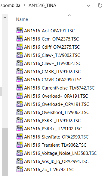
I agree that sometime it hard to run a TI opamp model, but I am not sure if TLV9062 is that hard to run. I suggest you also install TINA-TI if you want to work for TI opamp model as it can provide many useful information how that opamp model is tested by TI in TINA and how TINA is configurated to run that model.
For example, if you download TLV9062 Tina example, you can see none of its example actually simulate with single power supply.
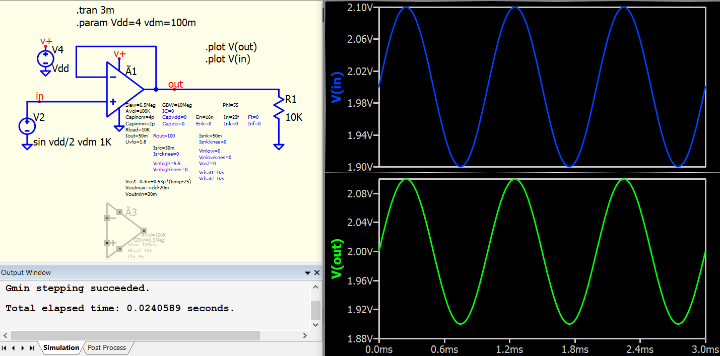
So, if I modify your schematic to dual supply, I can run this opamp in Qspice. I increase test signal frequency to show its output transition.
Just for your information, I found that TLV9062 Tina examples consist of method how to test different parameters of opamp. May be it can be a good reference guide how you can model a RROAMP to match datasheet response, as these examples provide test circuits for datasheet parameters. With that, you may setup RROAMP and verify effect of its device parameters to datasheet parameters
I will review that if I have free time, but I expect this may be a project needs weeks to complete.
The workflow I am trying to use is to run the TI supplied model in LTSPICE and use the frequency response from it to tweak GBW, Avtol, and Phi (in that order) of the QSPICE Ã device in circuit posted here: Op-Ed on Op-Amp Modeling. Then create attributes for other parameters included in datasheet. I was successful in doing this for TLV314 but it doesn’t work for OPA396 because it appears to have an extra zero and pole. These are both rail-to-rail op-amps and I’d be interested to hear if anyone else here can come up with a workable approach.