Do you have an example to demonstrate how that generated or how it look like. Frankly, if you need help from Mike, we at least have to demonstrate what that is, and why it is a problem.
I will firstly check with Mike about .ic and IC behave differently in using UIC.
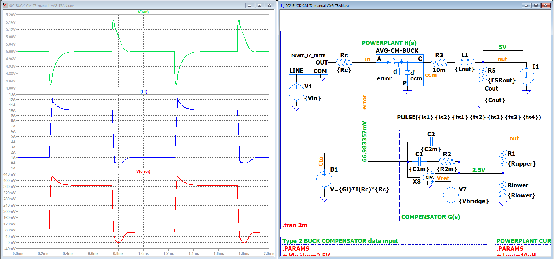
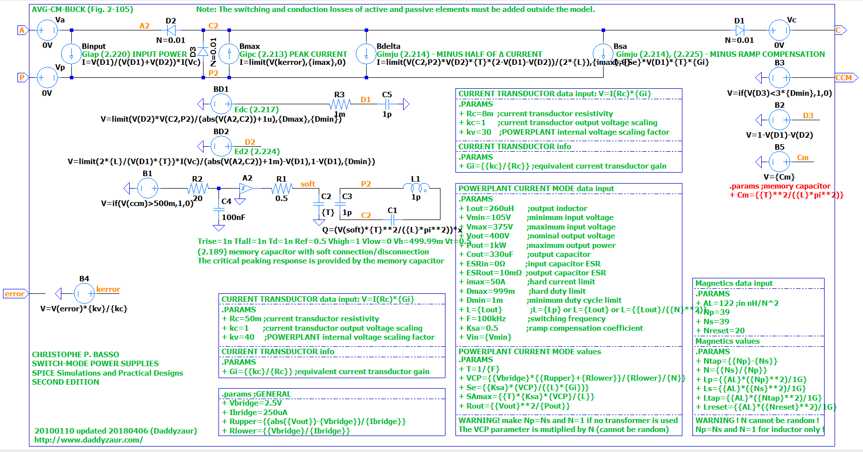
@KSKelvin, thanks. I already added here a complete and working model adjusted to work with LTspice, you can download the whole functional circuit: Current Mode BUCK Converter. It has the memory capacitor C1 in the AVG-CM-BUCK schematic model adjusted to work with V(soft) instead of V(ccm). Without smoothing-out this step the simulation will crash. Other simulation programs don’t need this extra smoothing circuit. I had to implement a dynamic smoothing, function of the switching frequency, took me a lot of time to figure out this one. Without the current spike now the model works as expected. You can even run in a matter of seconds a full Monte-Carlo analysis with hundreds of cycles for the phase-gain response of the loop, stepping multiple parameters.
I think LTspice made some compatibility changes and possibly is complaining or not now about some voltage sources defined with the wrong number of parameters. If you encounter any issues I can help to re-define the sources with the new LTSpice requirements.
Try it, you’ll be surprised. Only the average models can help in hardware design, if you need to make sure the product is not blowing up in some unexpected conditions. You will be able modify dozens or hundreds of parameters and find the worst possible case in a matter of seconds.
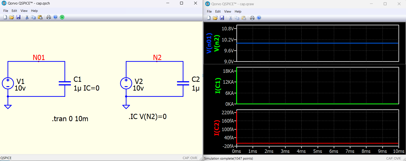
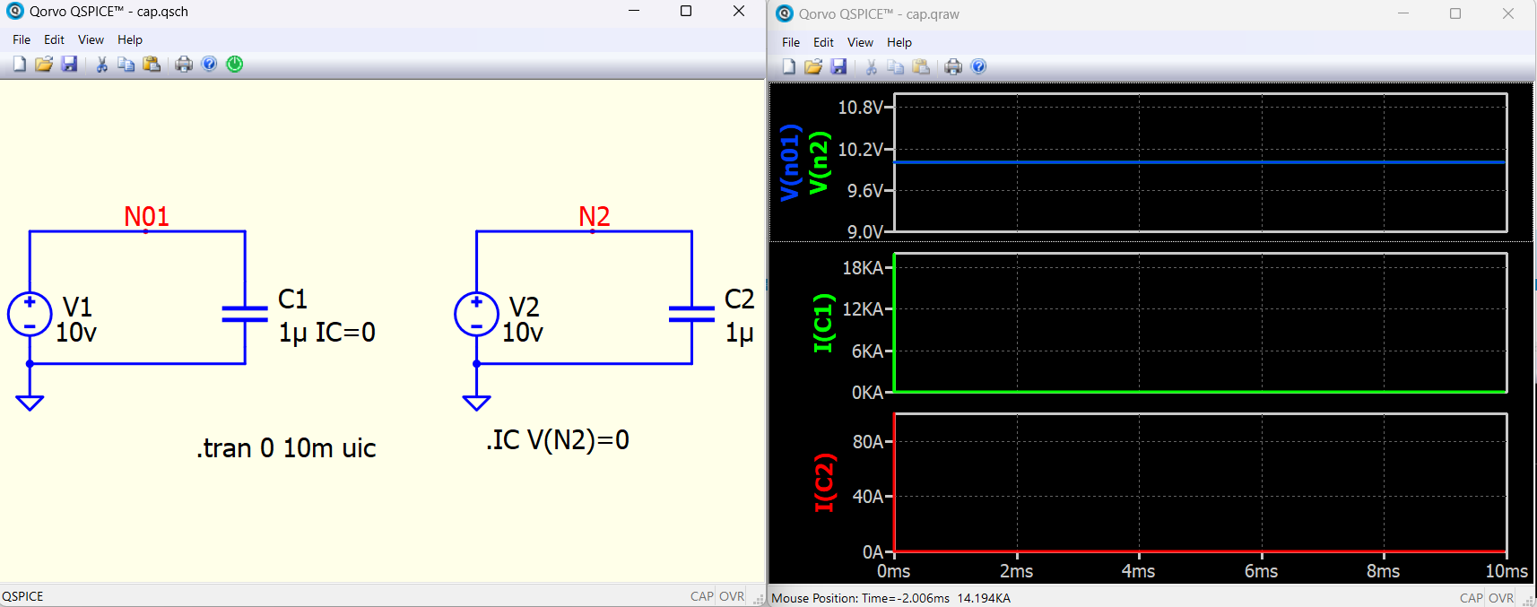
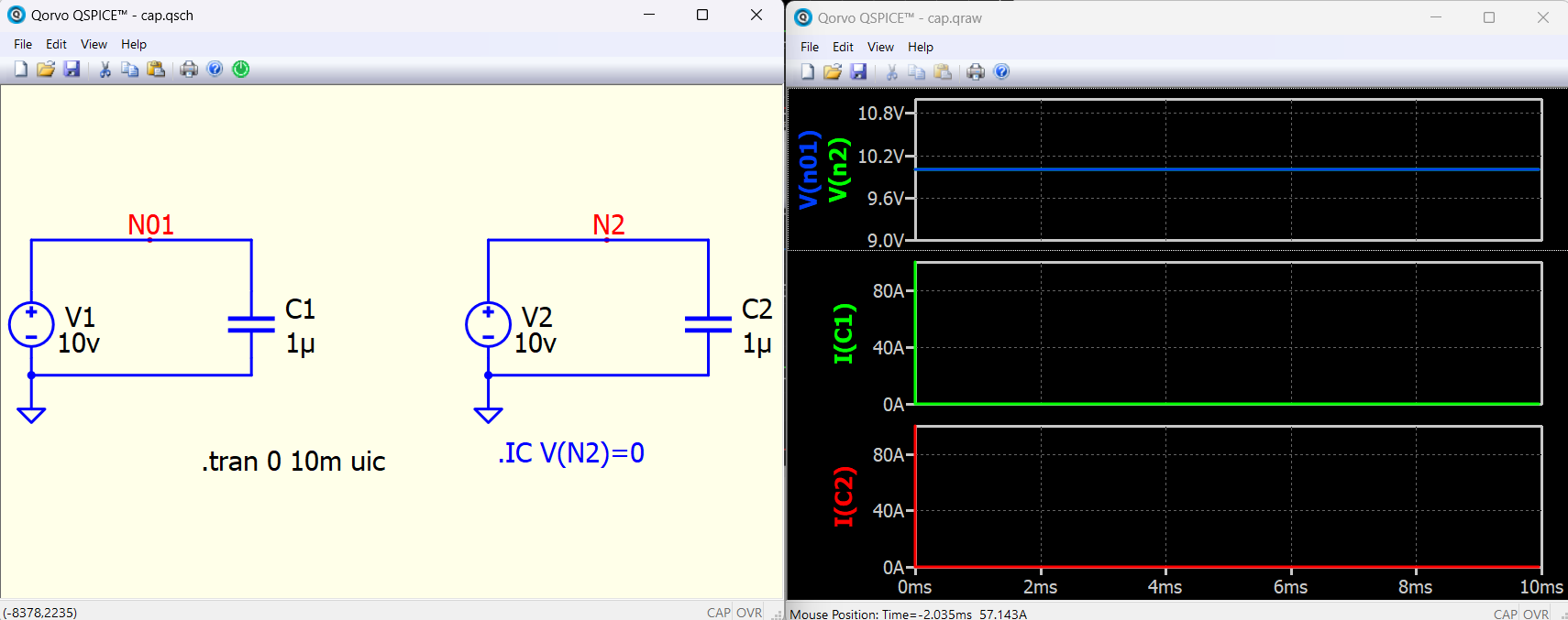
From my point of view the correct behaviour is that with large value of the current through capacitor (20kA or so (ideally infinity)) at t=0s and when having initial capacitor voltage set to 0V at t=0s (IC=0/UIC). Another question will be how that value of capacitor current is calculated? I am expected to be some hidden resistance within simulator/capacitor model or something that limit this current at that value, to not go up to ideally infinity value.
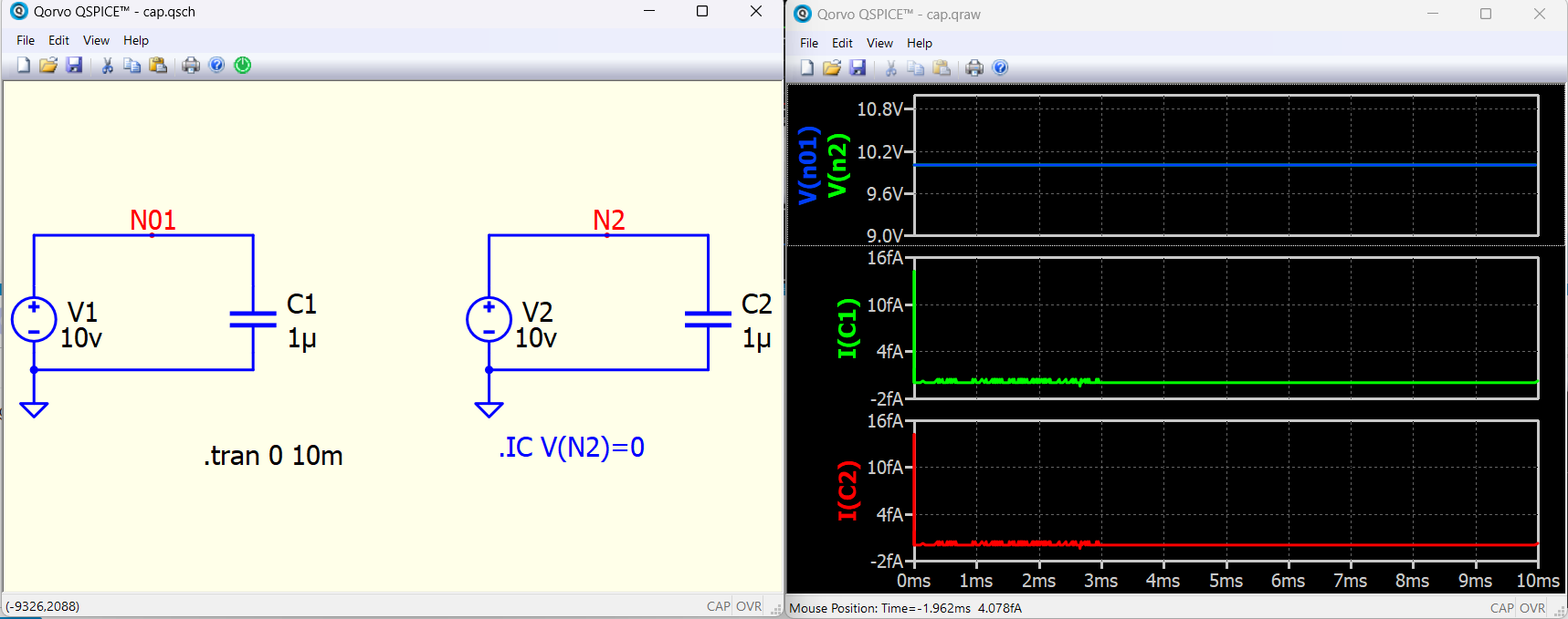
And as well, how that value of fA is reached when not having set IC=0 and not having UIC? And how that value of 100A is reached when not having set IC=0 but having set UIC?
@Cornel, probably the difference you see is because of the default simulation step. If you set max stimulation step to about 1 ps maybe you will see much closer values.
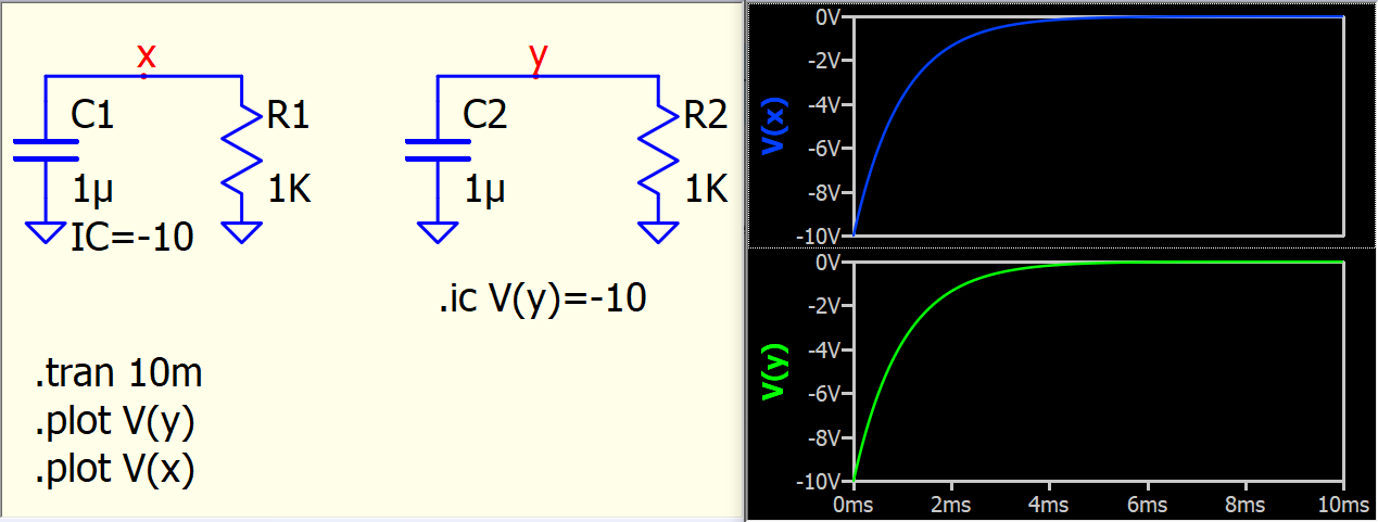
@Elisha Under what condition you find that problem? Here is initial condition with instance parameter IC in capacitor or .ic directive with -10V setting.
Any chance you rotated your capacitor by 180 degree in schematic? IC voltage is refer to capacitor + (node 1) to - (node 2) pins potential different.
Friend, in my old version of the circuit that dont work, but now setting the initial voltage is working, could be that the problem was the 180 degree rotation in the old schematic. i have also other problems with capacitors, sometimes i can not place capacitors in series, or add another capacitor to the circuit because the waveform viewer dont appear. look C3 in this circuit need to be disable to this circuit to work voltage_multiplier.qsch (7.9 KB)
.
This issue occurs due to the way the simulator handles initial conditions (IC) on capacitors. When IC=0 is set, it forces a sudden voltage change, potentially creating unrealistic, unlimited currents. To resolve this, avoid setting IC=0 directly on the capacitor. Instead, manage initial conditions using .IC directives on schematic nets or through the .tran command with UIC, ensuring more stable simulations.