This is also my results, as yours. I have Windows 11.
Probably this is another dead end. Unfortunately I do not see any point in posting about bugs and writing comments, it does not look like this stuff is monitored by the people who should.
@bordodynov, just one more side note here, I do not think at all that “a simulator should support models of other programs”, just the opposite. QSPICE and LTSpice ~should not~ support any other complex models of other programs. But, the basic standard models must be supported. I would say a normal capacitor and a blind generic opamp model would qualify for such requirements.
I get same results in Windows 10…
daddyzaur Ah, but from other point of views If a simulator can support models (more or less complex) of other programs then it will be great.
I do not see your point, why you want to be against this thing or to put this restriction, as for sure it will be more beneficial than just the opposite
Dude, it’s time to take it down a notch.
When knowledgeable folk have offered help, you have suggested that they aren’t smart enough to understand and aren’t worthy of your time to educate them. I don’t know if you’ve noticed, but the strongest forum contributors stopped responding to your posts a while ago.
QSpice has a single developer. He does not closely monitor this forum. Personally, I don’t want him spinning his wheels reading the forum – I want him focused on fixing and enhancing QSpice. If you have issues that you think warrant his attention, you can contact him directly using the link in the Help | About dialog. If you do, I suggest that you treat him with more respect than you’ve shown to others in this forum.
Alternatively, write your own Spice simulator and make it work exactly the way that you want. If you do, please make it a free tool and provide a support forum where folk can criticize your tool similarly.
–robert
4 Likes
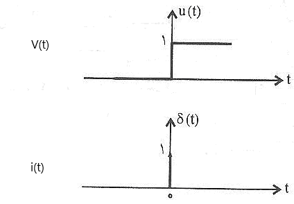
If you solve this equation with laplace. You can find that the solution of qspice is correct.
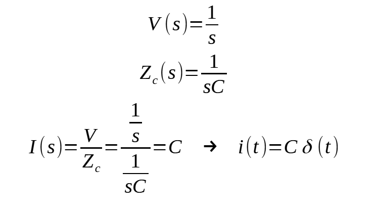
The solution is delta function that sholud be infinite when t = 0.
Best regards
@RDunn, Probably you have something specific in mind when you say “When knowledgeable folk have offered help, you have suggested that they aren’t smart enough to understand and aren’t worthy of your time to educate them”. Can you please clarify what you mean?
About Bug Reporting
If you refer to Qspice Help : Qspice > F.A.Q
- Bug Reporting : The official place to report a bug or reach the author is Mike.Engelhardt@qorvo.com
- Crowd Support : The official QSPICE Users’ Group is: http://forum.qorvo.com
It is common for people to assume that the official Qspice forum is a platform for reporting bugs. However, Qorvo or Qspice has not explicitly stated that the official forum is intended for bug reporting. It is important to understand that the forum primarily serves as a user’s group, and it may lead to disappointment if one expects it to function for bug reporting.
Nevertheless, the forum serves a valuable purpose as a community where members effectively assist each other. Valid bugs or suggestions for additional features can be communicated to Mike and potentially resolved. The forum acts as a front line for passionate SPICE enthusiasts who willingly contribute their extensive experience and knowledge to the community.
About this Case
In my personal opinion, when reporting a bug, the reporter has a responsibility to provide a simple example and clearly indicate what is being observed. It is best to include a simulation file so that others can easily replicate and confirm the issue (excluding new members who may not be able to upload files to the forum).
However, the main issue at the moment is that I still cannot fully understand what the problem is. If you are referring to a situation where a capacitor with an initial voltage of 0V in parallel with a voltage source generates a significant current spike at the first time step in a .tran simulation with UIC, I believe this behavior is expected. You mentioned that other spice platforms do not behave in the same way, so I set up an example in Pspice, and it exhibited the same behavior.
In your response, you provided additional information, but it was a lengthy and complex example involving simulating a SMPS with an average model. I became quite lost at that point.
In short, could you provide a simple example in Qspice, including the schematic and waveform, and highlight where you believe the problem lies? This would help clarify the situation, as I am unsure whether I am not understanding your question or if we have already addressed your question but you have not accepted the explanation.
3 Likes
In case anyone has questions about capacitor charging current, I have conducted a measurement using a 5V DC source and a 470uF capacitor. The measurement involved initially turning on the 5V DC source and then abruptly closing the circuit. As a result, a significant charging current (approximately 17A in this measurement) can be observed. This current is limited by the series resistance and the surge capability of the power supply. In theory, without any resistance and with an infinite current capability of the voltage source, the result would align exactly with what @ivan1 mentioned. Therefore, I see no issue with SPICE returning a large current at the first time step in a setup involving a voltage source in parallel with a capacitor and using the .tran UIC directive.
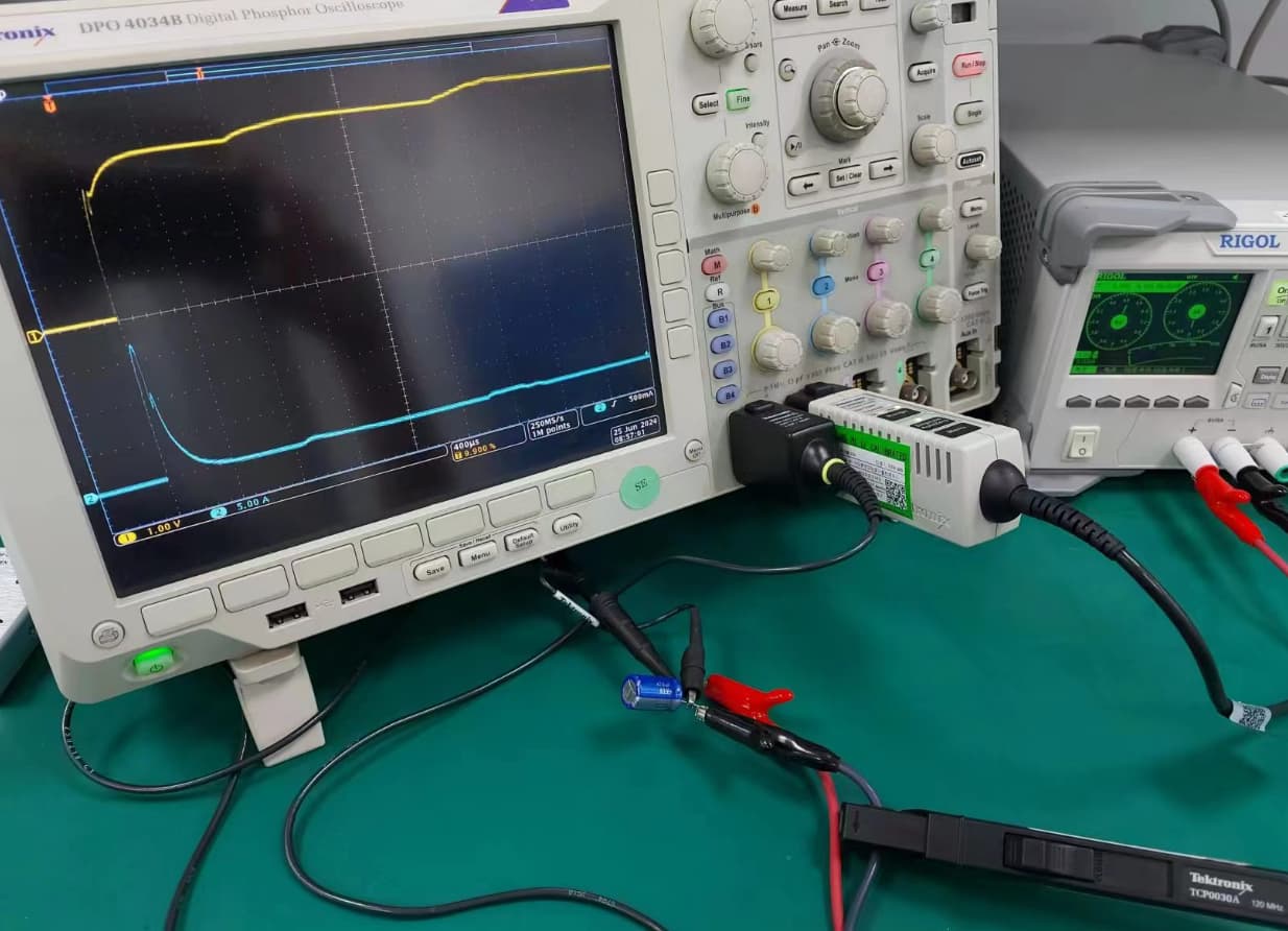
1 Like
KSKelvin I’ll explain a little bit what daddyzaur is unhappy about. I have Christophe Basso schemes in my examples. Daddyzaur claims that LTspice and Qspice have incorrect mathematical models of capacitors and because of this they cannot calculate some of these examples correctly. I tried the examples and there was no convergence in LTspice when calculating some of them. Christophe Basso built the bricks (subcircuits) with which he built his models. I think it is necessary to rework these bricks for Qspice. Christophe Basso’s results are remarkable and worthy of replication in Qspice.
Convergence problems? See https://ltwiki.org/index.php?title=Convergence_problems%3F
Wow, thank you! Without your explanation, I would have been lost in this discussion.
If I understand correctly, daddyzaur believes that LTspice/Qspice handles capacitors differently compared to Tina-TI/Pspice. Could anyone clarify what exactly the difference is? Is there a simple way to explain it? Daddyzaur seems to think that the spike current in the capacitor at the first time step with UIC is causing the convergence issue. However, it is worth noting that this characteristic is also present in Pspice (a simulator expected can work for this circuit). So, is this characteristic truly what prevents LTspice/Qspice from running Christophe Basso’s circuit? Or is the exact reason hidden somewhere else?
@KSkelvin, there are two parts of this issue. First, the visible side effect in QSPICE with a capacitor model that has a defined attribute, IC=0 for example, and not behaving as expected when you add or when you remove the UIC in the .tran command. In either case, the capacitor will behave the same, using the initial condition, with or without the UIC directive, showing a current spike that is expected when a step voltage is applied to a capacitor.
**
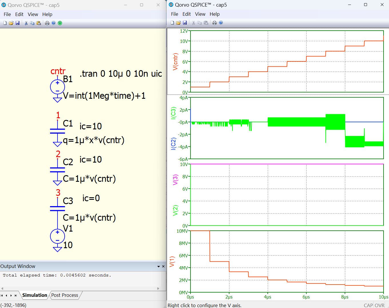
Now, the second issue is what I suspect is the root cause, and not anymore a side effect. I was able to put the two together because I discovered LTSpice and QSPICE, both of them, are implementing a capacitor model in a way no other SPICE simulation circuit does, including here not only Tina but Cadence and Simplis/Simetrix. LTspice and QSPICE breaks down in convergence errors with infinite current spikes when a capacitor is used as a variable capacitance, where the capacitance is an expression of some variable voltages. My suspicion, without any insight how LTspice/QSPICE implements the capacitor model, is that QSPICE calculates the amount of charge that must be added or substracted from a capacitor when the capacitance value changes and demands, accordingly, a sudden and unlimited current spike from the circuit in order to satisfy some internally imposed rules. All other simulators are simply changing the capacitance value without any other additional adjustments, hence you have a smoot transition, without any spikes.
**
And finally, I think this is THE major reason why LTspice and QSPICE breaks down with standard SPICE/PSPICE models, especially models with some tables inside. Whoever tried to use complex models from other sources in LTspice/QSPICE understands how difficult is to make these work.
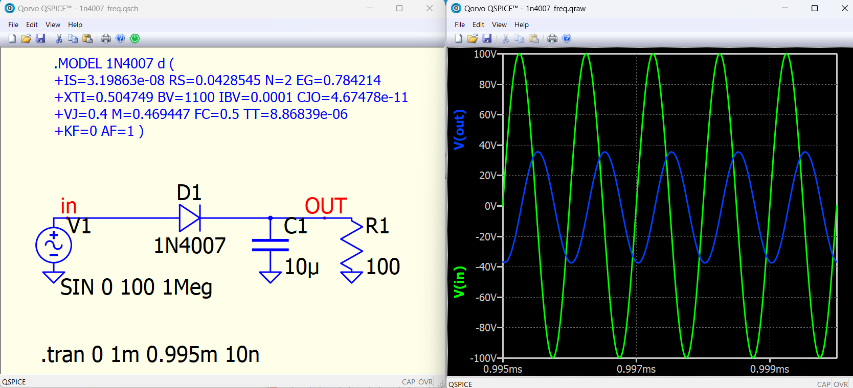
I am able to see this:
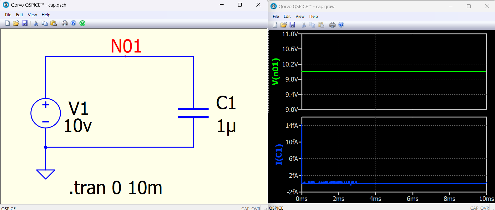
I am wondering @KSKelvin
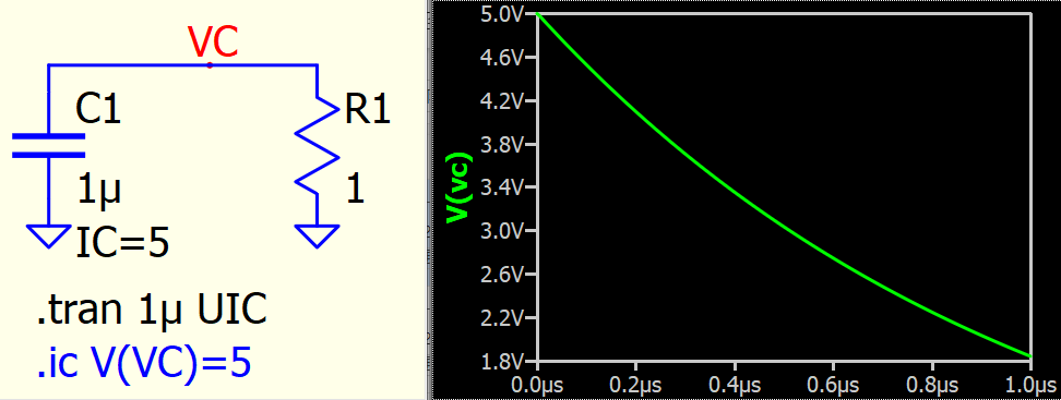
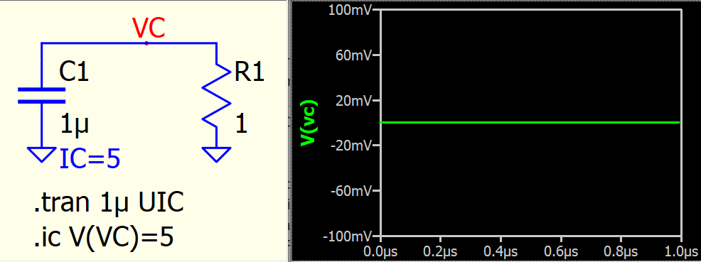
Why without uic and IC I can see that current of fA through C1 in 1?
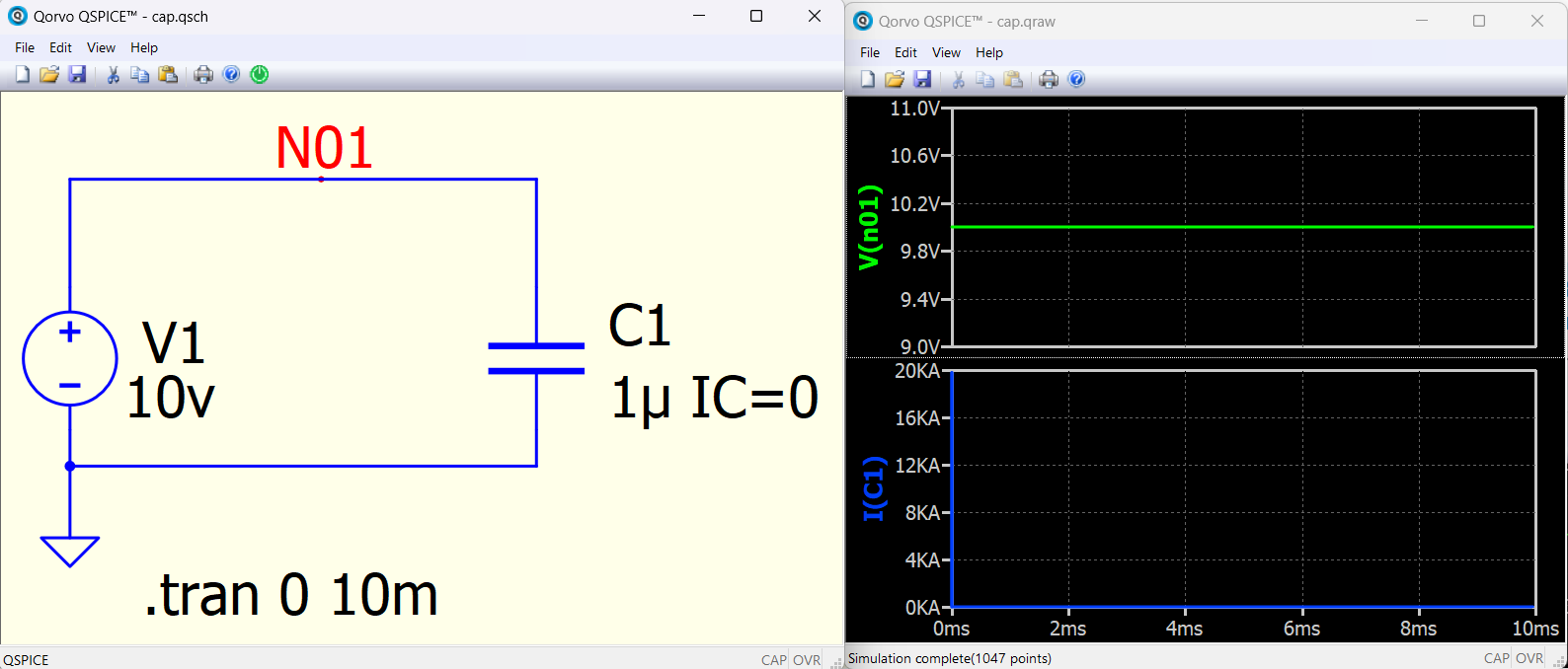
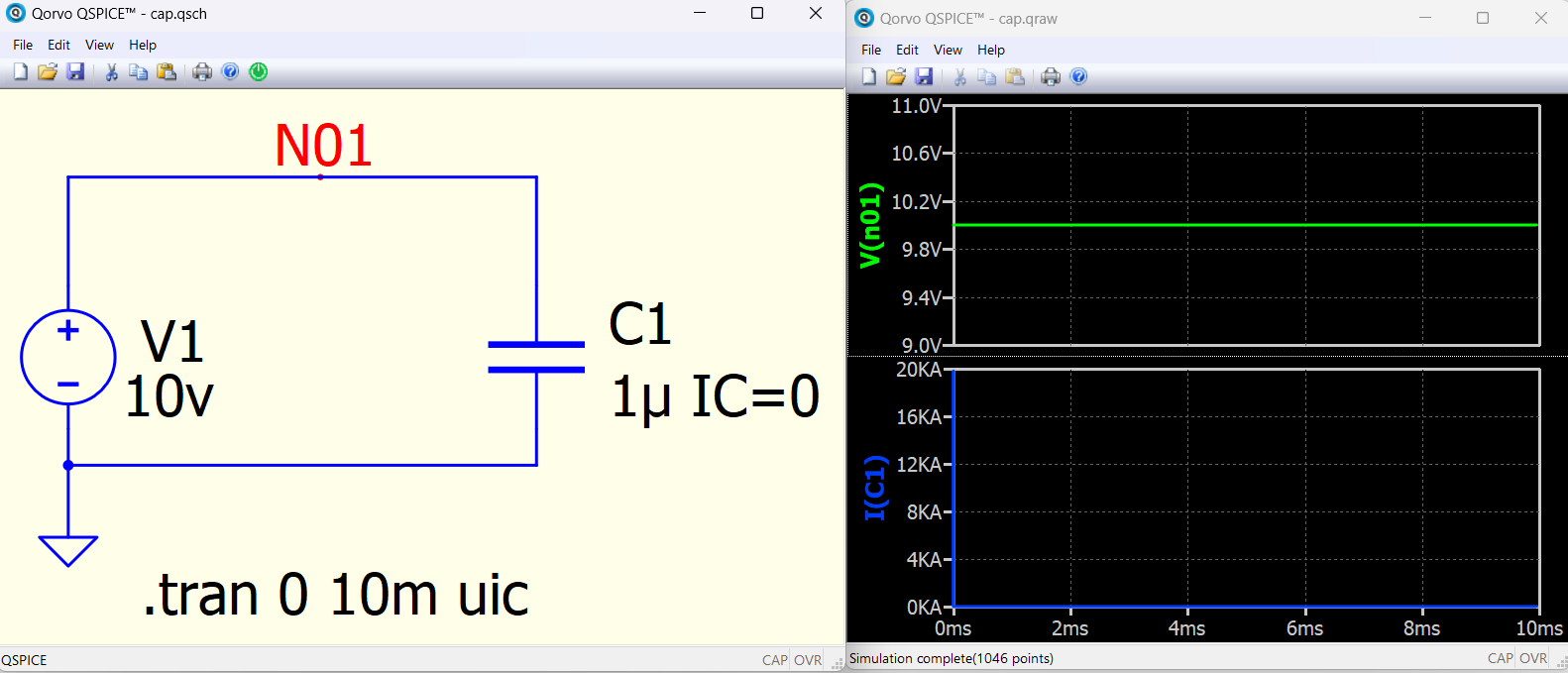
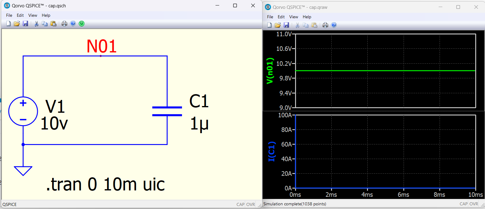
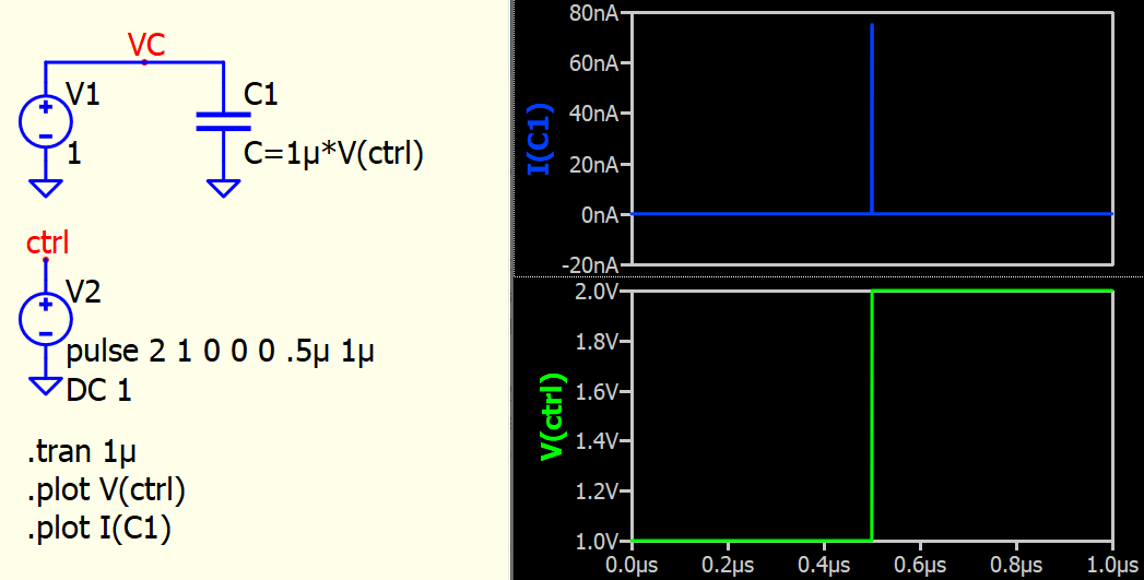
Why without uic and with IC=0 the current through C1 is 20kA in 2 and with uic and without IC=0 the current through C1 is 100A like in 4?
First part: Is this your concern? In both cases, the initial condition is defined. If the initial condition is defined using the instance parameter IC, UIC will still consider this initial condition. If the initial condition is defined using .ic, UIC will ignore it. Are you expecting that in both cases, the initial condition should be ignored?
I recall having an email with Mike in March regarding this matter. During that time, he was quite occupied with various issues. It is worth noting that Mike made an important comment regarding this. : But, in general, I’m never too worried about the solution after UIC. UIC means don’t do the .op, which means you’re insisting that it starts in incorrect state.
If you think it is better to align the behavior of using IC or .ic with UIC, I can try to report this issue again.
@KSKelvin @Cornel , yes, the first part is related to the property IC=SomeValue that cannot be disabled/ignored if it is in the capacitor model and you would try to use it with or without UIC in tran. To work around this issue, all you can do is to create two capacitor models, one with an IC=some value in the model, one without. Or add/remove this property for all capacitors in the circuit, as needed (not very practical), or create two versions of the schematic, one with initial conditions and one without. This part is critically important when you need to skip long simulation times and set beforehand some stable working conditions.
The second part is the main problem. To work around you need to create very complex circuits, tuned for the specific schematic nodes, that would smooth-out those pesky currents spikes. Without eliminating this issue the simulation will crash almost always, with convergence errors.
There’s another way. I’ve already suggested it. In Qspice there is another syntax for capacitor that ignores the law of conservation of charge. It’s C=F(x).
@KSKelvin , yes, it is related to this example. But you cannot always control the change conditions, and when the current spikes are going to infinity the simulation breaks. Slowing down the change speed, is one way of dealing with this issue but sometimes more involved changes are required. Models from complex circuits are very difficult to adjust.
You right, but also means you have to go through complex circuits and make a lot of changes. Even worst, what you think it woks in a basic example breaks down in a more complex circuit, because of that charge adjustment.