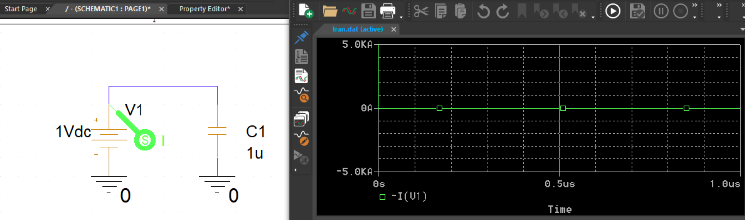
There is a bug making the normal capacitor model very difficult to use. If you set the attribute IC=0 for example in a capacitor that is connected to the power rails, then you can end up with arbitrary unlimited currents at the start of simulation. It does not matter if you add or remove the UIC in the .tran command. It does not matter if you place .IC directives in the schematic nets. The only choice is to delete the IC=0 from the capacitor attributes, otherwise you cannot use it.
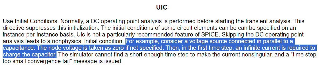
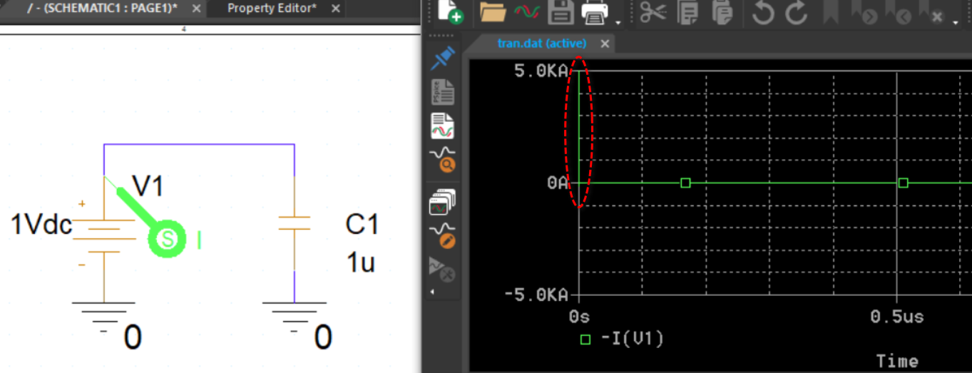
This is the help message in LTspice regarding UIC. When a voltage source is connected in parallel to a capacitance, and the node voltage is taken as zero, in the first time step of the simulation, an infinite current is required to charge the capacitor.
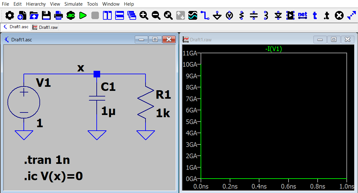
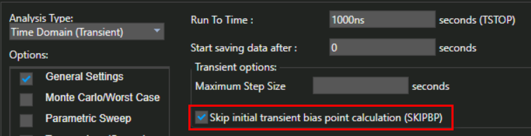
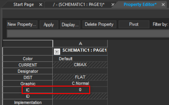
The purpose of the UIC is to skip the .op analysis before a .tran analysis and set every node voltage to zero, unless there is an initial condition directive specified. But if you set IC=0 for the capacitor (or use the .ic directive), it forces the capacitor voltage to be 0V regardless of with/without UIC. This situation precisely reflects the scenario in which a voltage source is connected in parallel to a capacitance with the node voltage assumed to be zero. Consequently, a significant current is expected in the simulation at t=0.
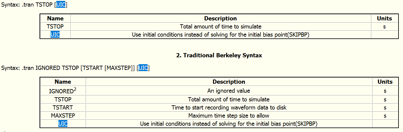
If you refer to my Command Reference Guide, you will find several slides that explain UIC, .ic, and IC= in the .tran section.
Qspice/Guideline at main · KSKelvin-Github/Qspice · GitHub
If you think about it, forcing IC=0 for a capacitor in parallel to a voltage source is causing a conflict of what the node voltage should be at t=0s. By the way, personally, I don’t see the significance of adding a capacitor in parallel to a voltage source in a simulation (unless the source impedance is defined), as the node voltage should always track the voltage of the source.
This behavior is consistent across LTspice. It always operates in this manner.
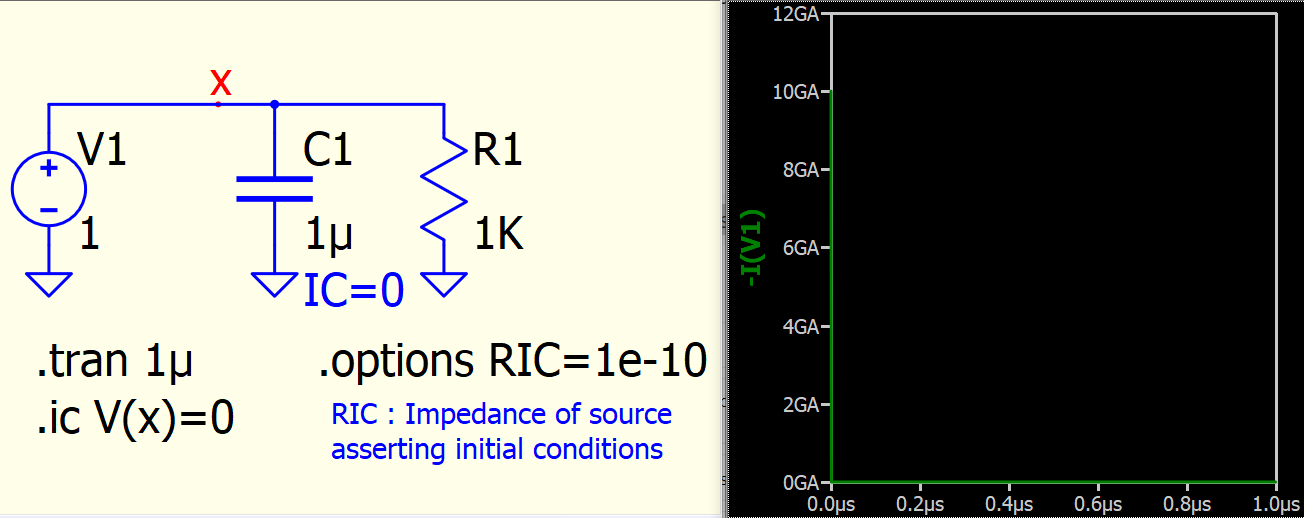
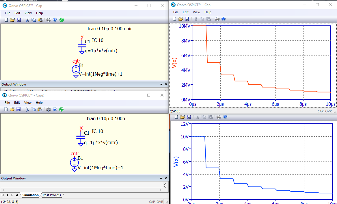
Here is an equivalent case in Qspice. Qspice with option RIC that control impedance of source asserting initial conditions which can affect current value in such initial condition.
2 Likes
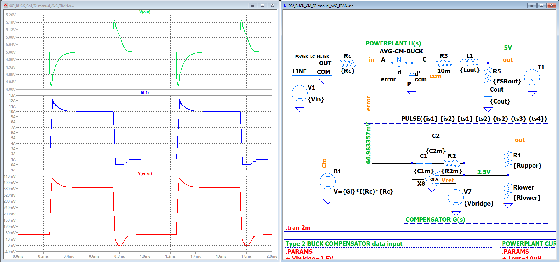
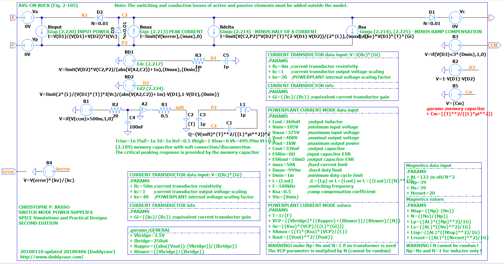
@KSKelvin, you’re right with your LTspice related explanation. Even more than you think. This capacitor issue is the main reason most of the standard SPICE models are not working in LTspice or QSPICE. To use the switched-mode power plant average models in LTspice I had to remove the current spike associated with bad capacitor models at the transition from CCM to DCM. The capacitor model is not adjusting the charge to the voltage specified as initial condition (as it is supposed to work), but instead is demanding the circuit to provide infinite currents to push the charge up/down in zero time. To understand the issue, you should check a bit the average models from the Current Mode BUCK Converter example I posted here (Basso), and see the lengths I had to go to avoid this LTspice/QSPICE bug: Current Mode BUCK Converter
Other SPICE simulation programs are not having this issue, the capacitor models are implemented the right way. Although, this discussion is pure academic as long as QSPICE (and LTspice) is not obeying the definition of UIC and instead is always enforcing the use of initial conditions: “It does not matter if you add or remove the UIC in the .tran command”
This is simulation result from Pspice. Initial condition of capacitor is 0, and UIC (skip bias point).
1 Like
Thanks @KSKelvin , that’s the whole point. Yes, Pspice, Tina, etc. etc. all of them are working as expected, per standard. Not LTspice, and not QSPICE. The standard capacitor model is messed up. Yes, I understand the desire to force the charge, the voltage, and the peak currents to match some logic rules, but the unintended consequence is infinite current through capacitors, leading to convergence errors.
This is precisely why nobody was able to to port Basso’s average SPICE models to LTspice, not even Basso! He had no choice but to offer his models in various other simulation programs, not in LTspice. Everybody that tried failed, because the capacitor memory used to switch from CCM to DCM in current mode control for current mode switched mode power supplies is pushing the currents to infinity when the transition happens. The only way that allowed me to port these models in LTspice was to add an extra circuit to remove the non-convergent spike. See below, and pay attention to the memory capacitor.
Sorry, I found I completely confuse what the problem is. As from Pspice, I also see a high current spike at first time step if IC is set to 0 and skip bias point, which is same as LTspice, Qspice.
Yes, but QSPICE is messing up the simulation either way, with SKIPBP or without. The problem is fundamental, LTspice and QSPICE is assuming that the sudden capacitor charge up or down must be provided by the capacitor connections, hence forcing the current to spike to infinity. All other simulation programs are adjusting the charge as needed, automatically, without current spikes, any time when you change the capacitance value. The initial condition bug is just a byproduct of this fundamental problem.
This is an imaginary problem. Putting a capacitor in parallel with an ideal power source is deliberately creating problems for yourself. Qspice and LTspice have an Rser voltage source. This parameter is not available in other programs.
Therefore, my opinion: when using ideal voltage sources (Rser = 0), do not bypass it with a capacitor. Doing so is stupid. Or at least use the Rser parameter for the capacitor. You will not deny that ESR exists. Regarding the unsuitability of some models for LTspice. I have encountered this more than once. Then I simply adapted the models. I have always succeeded in this. And some of the techniques I learned allowed me to speed up the modeling. This was especially true for DC-DC chips from TI. In Qspice, controlled voltage sources now have an Rser parameter. This allows you to reduce the number of nodes in the circuit. For example
A logic element is built from a dependent voltage source with a logical function. Next comes a resistor, and then a capacitor. The resistor can be added to the Rser of the source. This removes the bad node with a high slew rate. Double win.
@bordodynov , I see your point about stupid people. Unfortunately is not a matter of adding or not some parasitic resistors, is the response of QSPICE with or without UIC in the .tran command and/or SKIPBP. There is no way to run a simulation in QSPICE if you make the mistake to add .IC in the definition of a capacitor, since adding or not SKIPBP will do nothing.
The real fundamental problem is the handling of variable capacitors that would necessarily translate into variable charge. Think about a capacitor value that is function of a digital voltage, as is the case with average models for current mode controlled power supplies, when the capacitors are used as memory cells. A capacitor memory cell demands no current spikes, and needs adjustment of the capacitor charge as necessary, without current spikes. Unless any other simulation program, QSPICE and LTspice will generate infinite current spikes any time when you try to use a capacitor in such a scenario. That is the fundamental problem. And yes, I think is the reason behind the issues with .IC in the definition of a standard capacitor.
@bordodynov , there are two problems you should pay attention to. First, it is not up to you to decide if an option is worth using it or not, it is about the circuit requirements. It is very important to have this option working as expected. Most of any circuit will be outside your analysis skills if you cannot set up some initial conditions. Second, the fundamental problem with the way QSPICE and LTspice is messing up the capacitor definition: the charge conservation enforced here is making the current at the capacitor pins to go bananas any time when the capacitance is adjusted.
If you payed attention to the average models you posted on your site, then you should be able to identify the issue there. The current mode control average model fails to simulate, because the capacitor value change will break the convergence (at CCM/DCM transition). All other circuit simulators are working as expected, without this issue.

@bordodynov , adding comments would help understand what message you want to pass along. I see you added some ESR resistors, and in the body of these posts was specified a few times this matter is not related to serial resistors. The issue at hand is related to what seems to be a conservation of charge rule enforced on capacitor models, with immediate effect on infinite currents. The matter is very visible if the capacitor has an IC property, but the real annoying issue is the variable capacitance that also pushes the currents to infinity. This alone is the main reason why LTspice and QSPICE fails with convergence errors for most of the PSPICE models. It is true if you add resistors you can dull the current spike, but is also true if the voltage on the capacitor is equal with the power supply voltage (as is the case when you do not skip the initial transient bias point calculation) then the current spike should be also zero. If the conservation of charge is not enforced and the variable capacitance is changed conserving the voltage at the capacitor terminals (like any other SPICE simulation program does, except for LTspice and QSPICE), then you have zero current spikes with variable capacitors or after calculating the initial bias point, and all these pesky infinite current spikes and convergence errors will be removed. More details are in the post. Also, it would be great if we have a checkbox with the option to conserve the charge for a variable capacitor, if conserving the charge is so important. Probably I missed the real point you try to make, and indeed you see something there not related to resistors?
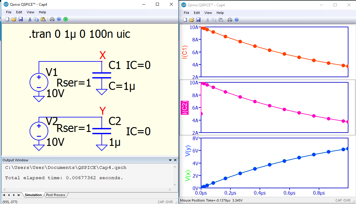
I just discovered that there is a second version of the capacitor model. In it, the capacitance value is set as follows: C=value. And it doesn’t have a huge current surge when connected to a voltage source. I added resistors to the source to show that it is a full-fledged capacitor, only it doesn’t give a huge current surge. And that’s what you wanted.
@bordodynov , no, not really, I am not very interested in special components to implement standard functions, you got it upside down. We should be able to use standard models with QSPICE, and skip the tedious work of chasing down endless netlists for special parts replacement.
And again, you forgot the issue with variable capacitors that will push the currents to infinity. I have to implement complex smooth-out circuits tuned for an application in order to use variable capacitors, otherwise QSPICE or LTspice will not work, crashing with convergence errors.
daddyzaur,
sorry, but I doubt your statement. Give an example in which the “wrong” capacitor appears. Exactly when Qspice can’t calculate the circuit because of this.
I think that the capacitor model in Qspice is physical. The charge conservation law is fulfilled, and in other programs the model is not physical - not real, does not obey the laws of physics.
@bordodynov , you already have the average models for AC power supply analysis listed on your webpage, with many examples. I just assumed you created these models since you do not list any source you copied them from. It is just reasonable to assume you know already how an average current mode model with CCM/DCM discontinuities works, how the transition is implemented with a memory capacitor. There is your “wrong” capacitor as you call it.
I would not call that capacitor “wrong” but “standard”, and I have no idea where a “physical” capacitor fits in here. You have to take it out on Berkley and all other SPICE simulations programs, I cannot help you. Go and argue with them about the conservation laws. Tell them that instead of simply changing the capacitor value without any other circuit corrections they have to conserve the charge.
Berkley’s Spice developers are no saints to me. I compared the programs. In one of the comparisons, I examined the performance of a 1n4007 diode half-wave rectifier at 1 MHz. It turned out that many programs show successful straightening, unlike Qspice and LTspice. I was very surprised. I checked several programs.
I do not believe that a simulator should support models of other programs, although it is desirable. They may have different syntax. It is advisable to adjust third-party models for a specific simulator.
I haven’t worked on Basso models. I just copied the files just in case I needed a small signal DC-DC model.
I will make an attempt to modernize the Basso models.
https://kazus.ru/forums/showthread.php?t=120932&page=39
If you manage to access the link, you will see that many spice programs lie. In the pictures I wrote which programs I used. And what do you say to this?
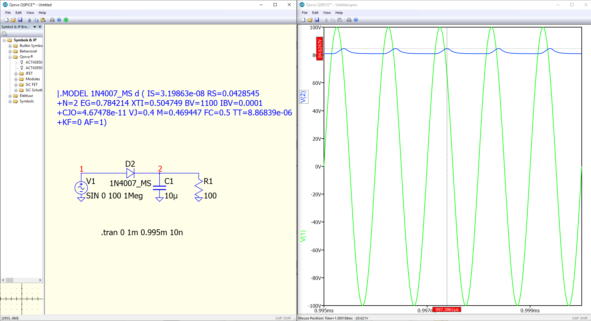
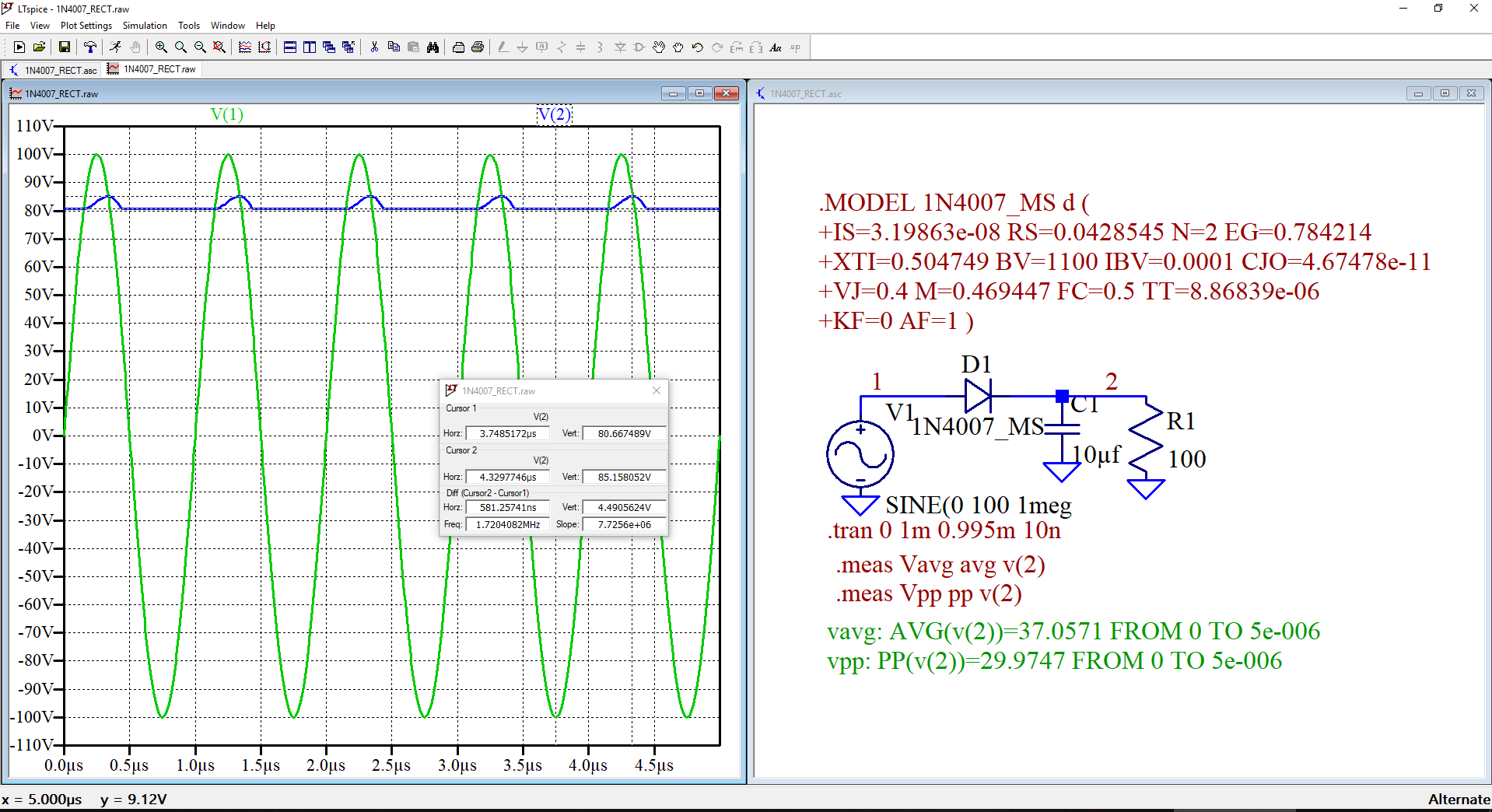
I got a completely different result!
Does the Qspice result really depend on what Windows system is on the computer?
I have Windows 11.
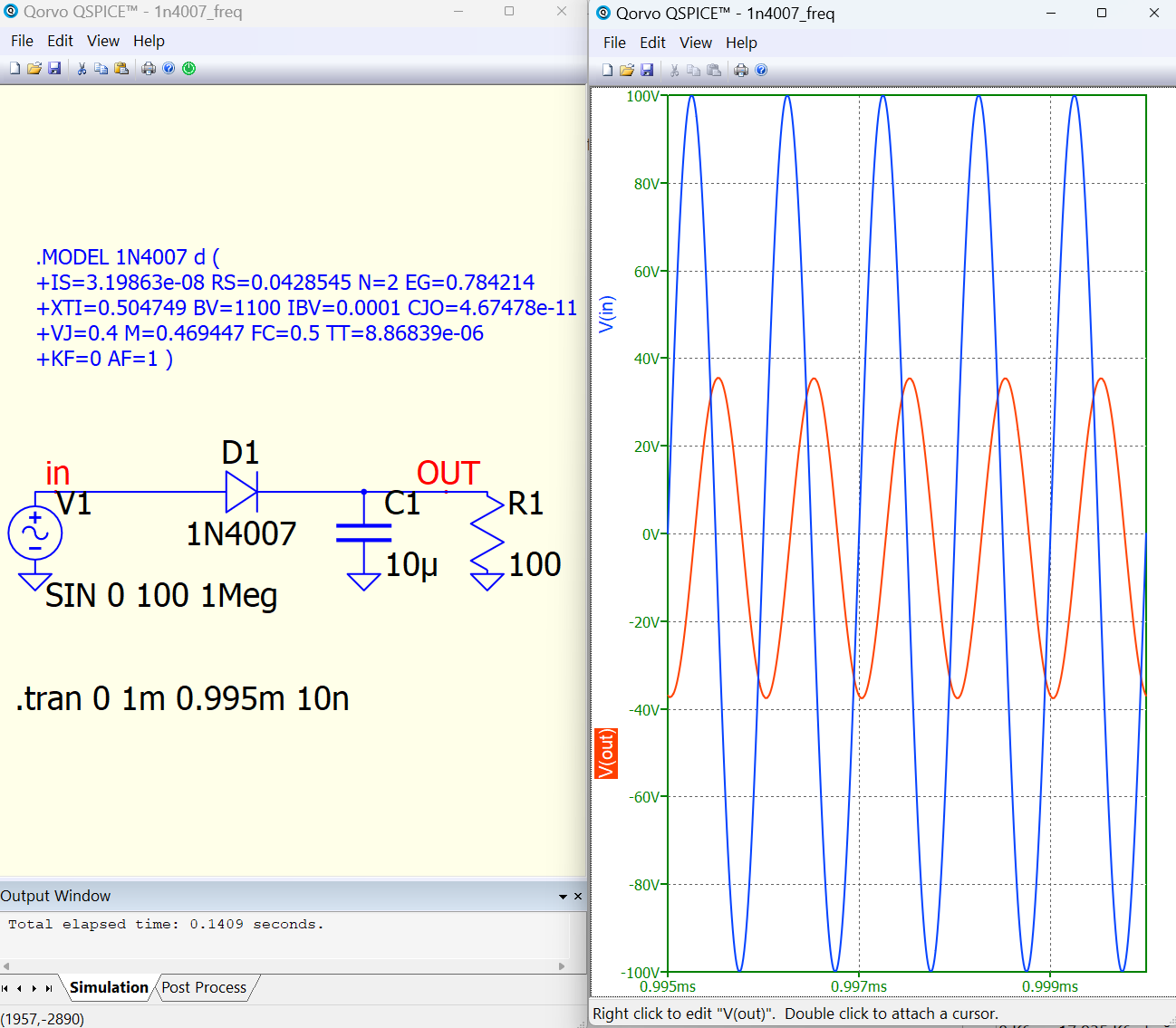
1n4007_freq.qsch (3.2 KB)