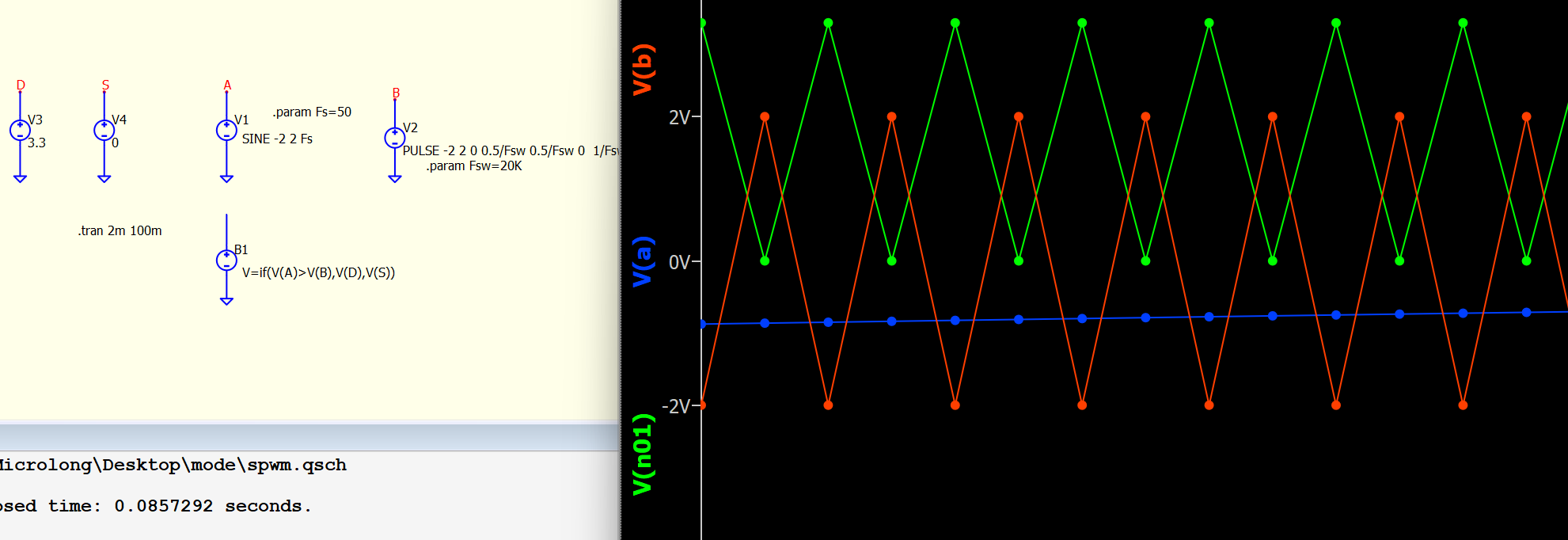
there are several items have to consider, but can you upload the schematic?
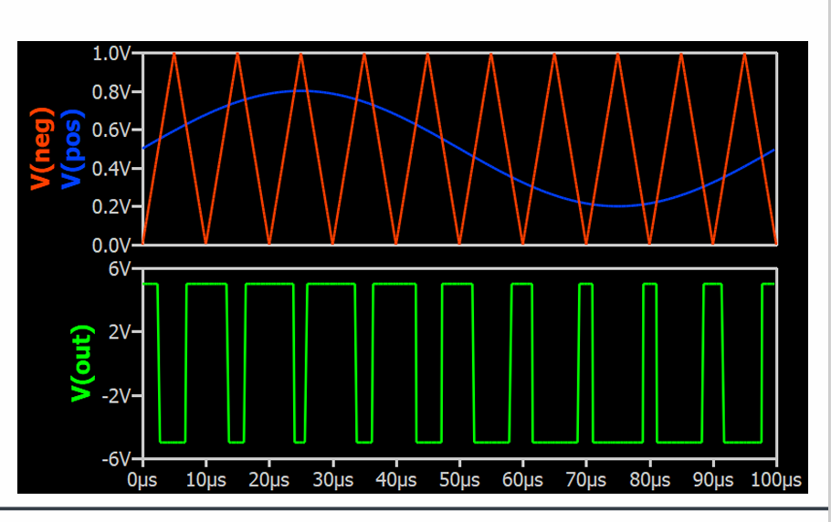
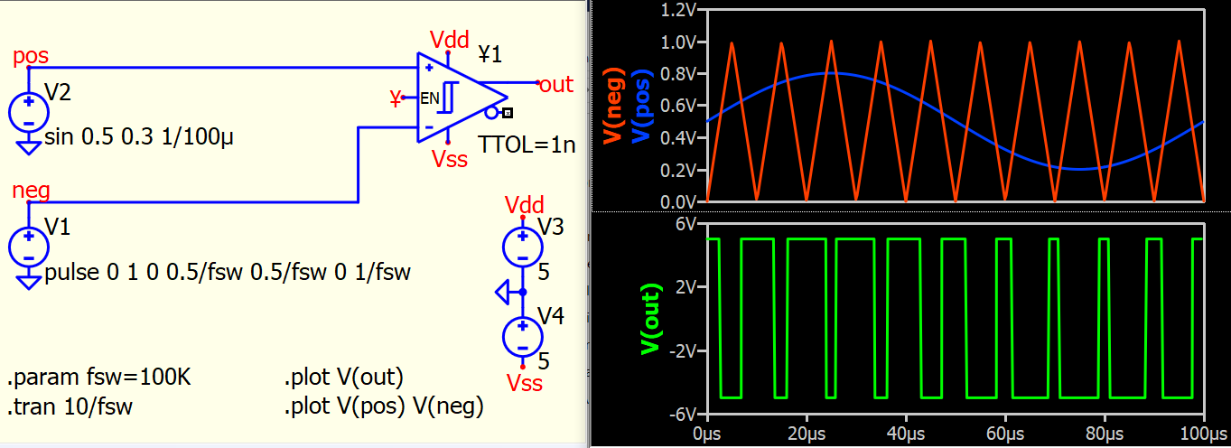
This is the method I would recommend.
- Use ¥-device HMITT as the comparator instead of a B-source, as we can take advantage of TTOL in ¥-device.
- ¥-device with TTOL, this will eliminate the requirement of maxstep as its can reduce timestep at output change its state, which give you fast simulation time but good switching waveform. For more information, take a look of this post
TTOL device to Interface analog and digital - QSPICE - Qorvo Tech Forum
PWM.qsch (5.2 KB)
By the way, I believe there might be a misunderstanding regarding the syntax of the .tran command. You can refer to this post for more information. Since you didn’t upload your schematic and I’m feeling a bit lazy to build it myself, I’ll just give you a quick reminder. I think my last post should address your issue by suggesting an alternative way to implement what you need.
Why are the simulation results different after updating the program? - QSPICE - Qorvo Tech Forum
Thank you very much for your response, it was very helpful. However, as a new user, I am unable to upload schematic diagrams. Thank you nonetheless.
1 Like