currently I am getting familiar with simulating compensators by implementing them using analog circuits using op-amps along with R, L, and C components. Is there a way to simulate them by way of a discrete difference equation as you would with a microcontroller?
For example, something like this:
  --- array of output measurements ---
  u[n]      -> current result sum
  u[n - 1]  -> previous result sum
  e[n]      -> current error
  e[n - 1]  -> previous error

  --- Discrete PI compensator ---
  u[n] = u[n - 1] + Kp*e[n] - Ki*e[n - 1]

  --- PI compensator in SW ---
  y_out = prev_yout + Kp*error - Ki*prev_err;

.
.
.
  /*
    Code to update actuator (i.e., PWM) value here - pending
  */
.
.

  // Update history variables with latest values
  prev_out = y_out;
  prev_err = error;
Here is a PID project that @RDunn and I collaborated on, which is hosted in @RDunn’s repository. While we can implement this in more advanced ways today—such as moving the clock from external to internal—that example still serves as a great starting point.
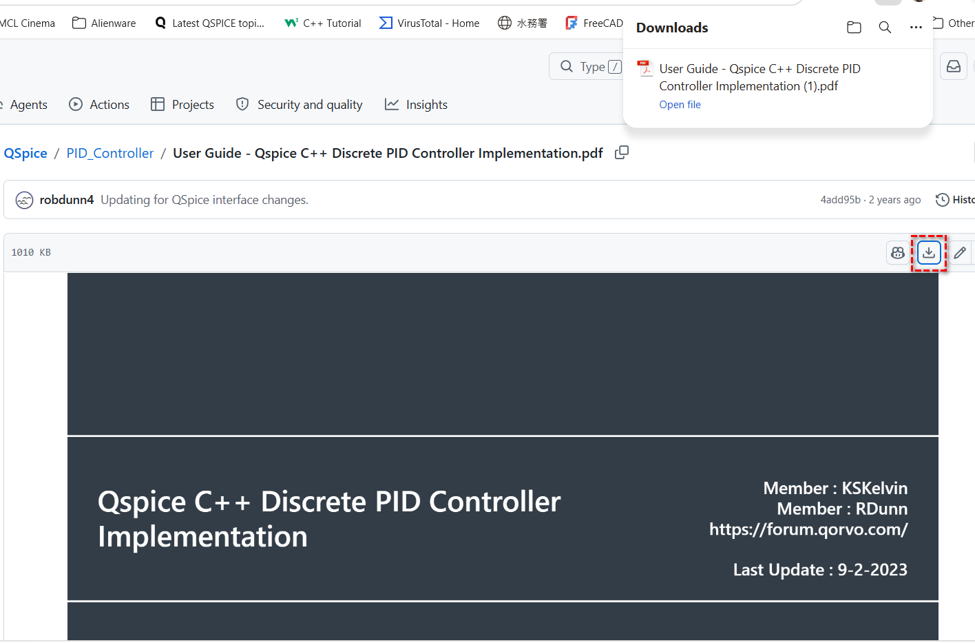
Thank you @KSKelvin for this lead. I will have to review @RDunn’s GitHub. For some reason, when I attempt to download the user guide, I am getting a busy signal (tried about ~5 times):
I quickly scanned the tutorial and encountered the part where it states that the switching frequency is 50 kHz and the sampling frequency is 1 MHz. Is this practical or ideal? I thought one would normally sample when switching.
The sawtooth is a continuous time signal and the output of the PID is meant to be a sampled version of the continuous time so, they chose to sample it at 1 MHz / 50 kHz = 20 times the sawtooth’s frequency. Remember to make a distinction between the switching frequency of the controller, and the sampling frequency of the signal(s). The former does, indeed, set the sampling rate for the controller, such that the analysis of the gain is done relative to it but, the signals, themselves, are analog by nature and, in order to match them with a sufficient bandwidth, that 20x sampling was chosen.
I’ve actually seen in practice where the sampling frequency is the switching frequency in SMPS units - this is when the PWM value gets updated based on the latest measurements. If you’re oversampling above the switching frequency, and you’re not updating the PWM based on this oversampling, is this not a waste of bandwidth?
Note that I am bit new to this part of the design process so my understanding is a bit limited so forgive me if I ask what may seem as obvious questions. Is it not the sawtooth frequency the same frequency as that of the switching frequency - when the PWM duty cycle gets updated?
Like I stated above, I have observed where these are one in the same.
It seems here as if they are oversampling to get as close as to the real analog signal then sampling off of this signal (hmm?). This appears a bit redundant. I would just sample from the original signal and skip the middleman (i.e., oversampled signal).
@qspice_newb, no…sampling is digital control is typically done at the same sampling interval or greater than the PWM period (Tsampling = k * Tpwm, k ∈ 1,2,3,…). there is no practical use of running sampling at the smaller interval than PWM period since PWM duty can also only be calculated once for each PWM period.
There is a caveat though, there is a technique called “oversampling” where you can perform the sampling rate at smaller interval than the PWM period. However, in this case the controller calculation will still run at Tpwm interval with the input data taken from average of the measurement throughout one PWM period. Note, most commonly used oversampling rate is 4x.
in short, with PWM = 50kHz, you can run your sampling at 200kHz (for 4x oversampling) or at 50kHz, 25kHz, 12.5kHz for synced or down sampling.
If it is being oversampled, realistically the PWM will not get updated until the next PWM period (switching period), correct? That is, the duty cycle can only be updated during the switch sampling periods but not the oversampling periods. The oversampling is obtaining most up to date information in between the switching periods (PWM).
Am I understanding this correctly? If not, where am I going wrong here (I do understand that a microcontroller can oversample. Just need to clarify what it does with this most up to date information is all)?
Hi,
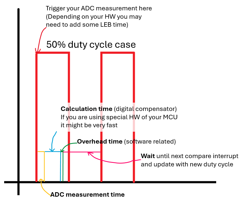
I believe a graphical representation of the chain of events happening in digital control could help you make your own C-block for controlling your power converters. Sampling and discretization is important if you want to be accurate with simulating digital control.
This picture is very generic and it is not covering all cases. There are others, but for starting point you can try this.
The example you saw in @RDunn’s and my work was developed to demonstrate how to use a DLL block to implement a discrete PID with external clock-based sampling. The sampling rate was set very high to closely match the results of an analog PID.
For switching mode power supply, when designing control loops, the closed-loop crossover frequency is typically set below one-tenth of the switching frequency (in considering Nyquist limit). Therefore, sampling the compensator at a frequency higher than the switching frequency is generally unnecessary in considering where the crossover already is.
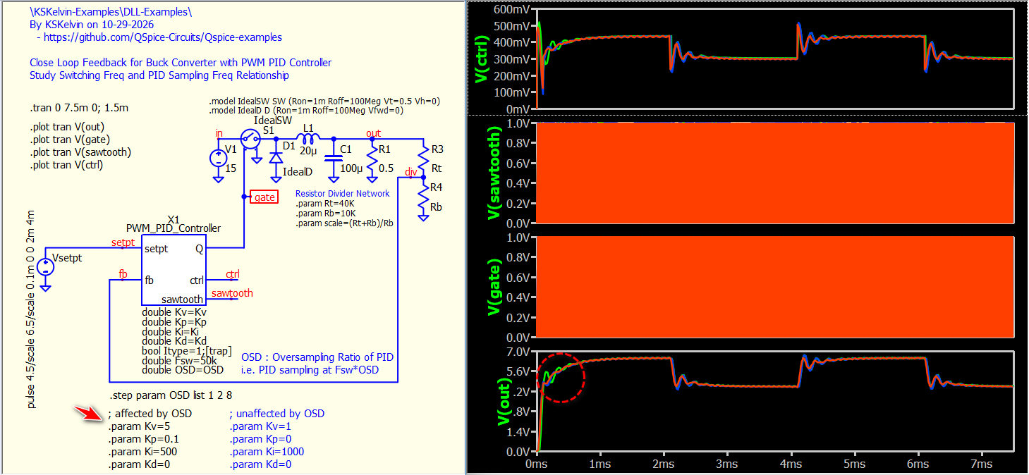
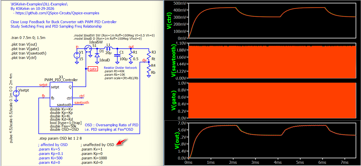
This example evaluates PID oversampling (Fpid = OSD * Fsw). For the PI setup (set for higher crossover frequency), output response deviations during large-signal swings, but almost same in smaller signal. For the integral-only controller (set for lower crossover frequency), the responses overlap across nearly all cases.
Yes, this aligns with my experience and observations in practice.
Thank you very much for providing a working example. Soon enough, I will be tackling the discrete time compensators so this is good to have and look forward to it.