I would like to measure the power consumption of the DWM3001CDK.
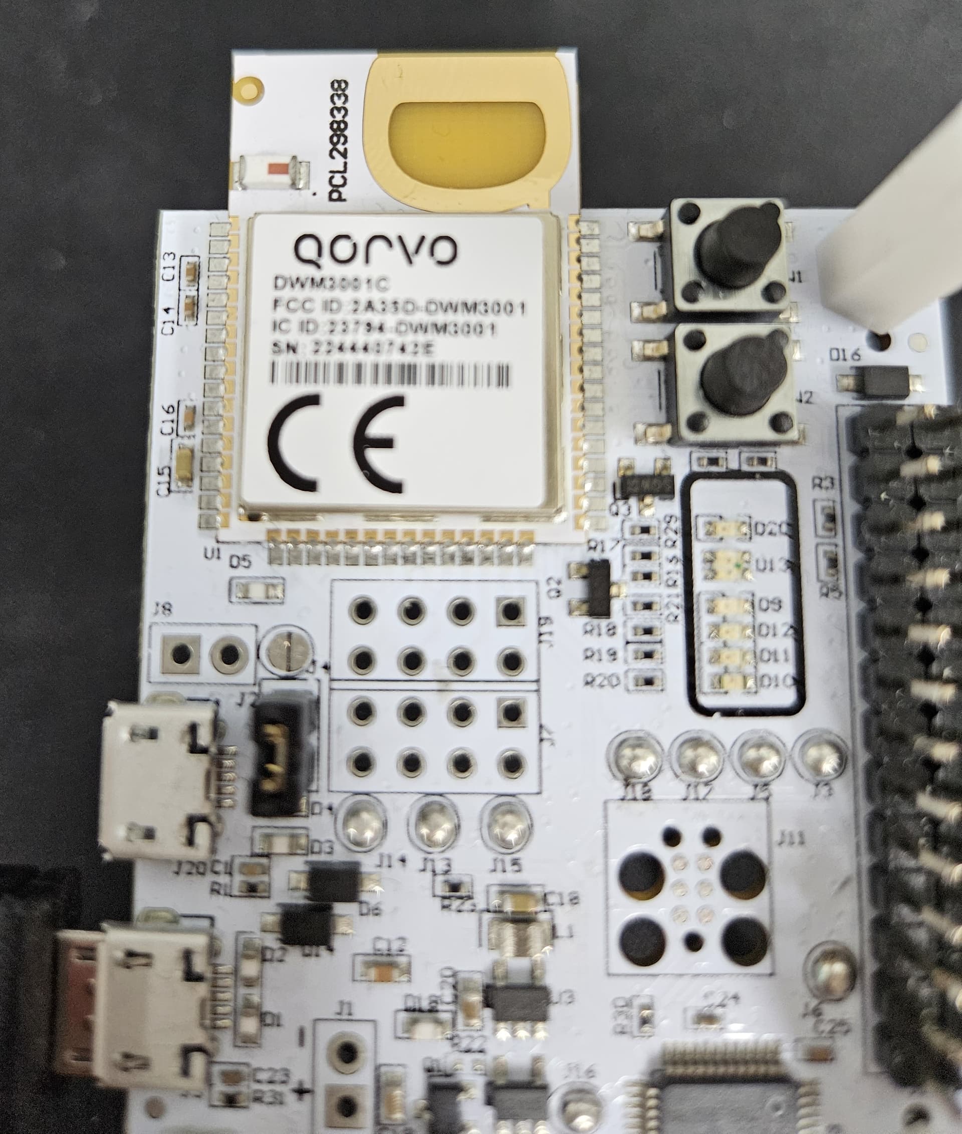
I am trying to follow the instructions in the link below, but I noticed that the solder bridge jumper on J4 is already desoldered. While J6 and J16 are soldered, J4 is not.
Could you please provide some assistance with this? Thank you.
Hi @kjun2288
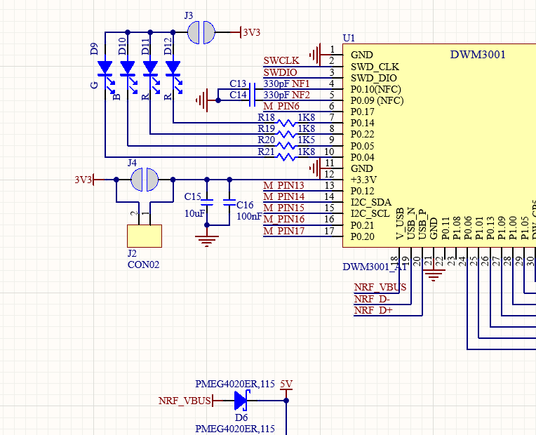
is the J4 unsoldered from the factory? If the J4 is unsoldered then the J2 is supposed to be soldered and jumper must be populated on it as without it the DWM will not work.
Hi @kjun2288
from the picture the J4 is already break and the J2 connector is soldered with the jumper on it.
There are various setups for the current measurements. The most accurate is to remove all solder joins to fully disconnect the DWM1001 - this sill disconnect the segger IC and other related stuff which add some additional positive or negative leaking current. But also you will loose control over the DWM1001.
How do you want to measure the current? What tool do you want to use? And now precisely you wan to measure it?
Unfortunately there is no simply way, every connected GPIO line can/will lead to some increased/decreased current consumption. And when you go down to few uA this becomes super important. For proper measurement you need to disconnect the DWM3001 from anything that might affect the current consumption. → Thats practically all - SWD, UART, LEDS, RESET…