Hi, I recently purchased 3 DWM3001CDK modules for one of my project. In which I want to configure 1 as anchor and other 2 as tags and want distance of these 2 tags from the fixed anchor, I flashed UCI firmware in it, and getting the readings on Qorvo one TWR gui but I want these reading in my python program, I am not able find any documentation on that.
Hi @akash,
Thanks a lot for the guidance!
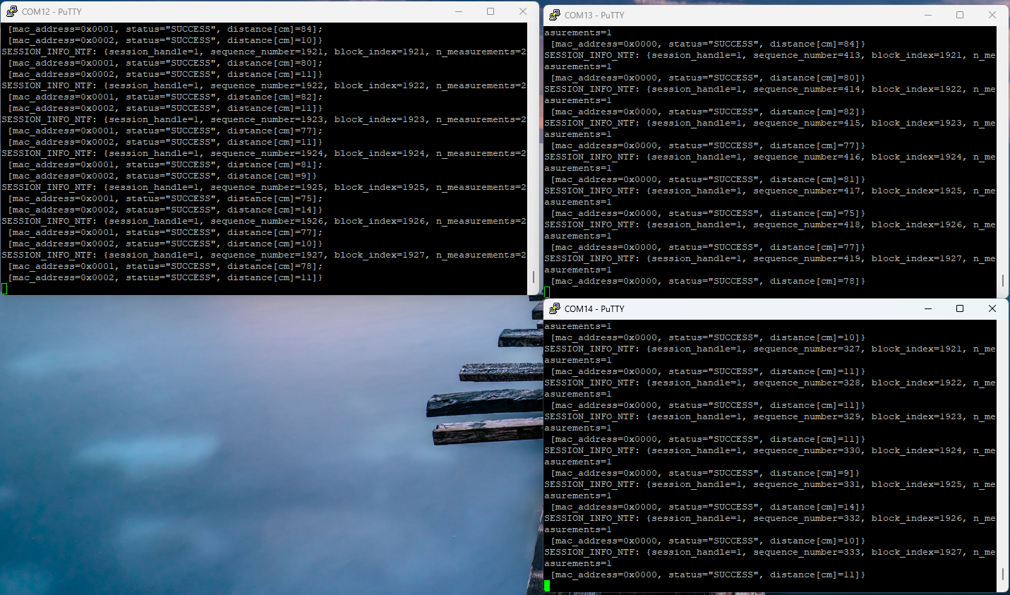
After following the guide, now I am getting data on putty terminal but the readings are fluctuating a lot, is this the expected behavior or I need to calibrate antenna in order to get the stable readings ?
Current setup:
3 DWM3001CDK placed 20cm and 40cm apart from anchor.
I did manual calibration with command calkey ant0.ch9.ant_delay
but readings are still fluctuating with ±10cm range. I am wondering is there any averaging method available in the sensor to get more stable readings ?
Hi @shashwat , as you are looking at the raw values, this level of fluctuation is expected in the distance measurements as we are not doing an averaging in our software. This is something that you would have to implement.
If you are concerned about the measurement not being close to the 40cm/20cm, then that would be antenna delay related. See this response from AndyA regarding using 3 boards in a triangle to do the antenna delay calibration: Calibration issues with UWB - #4 by AndyA
Hi @akash ,
Thanks a lot for the response, after implementing averaging and better antenna calibration i am satisfied with the result.
I have one doubt, right now I am manually sending the initf, respf on every start in order to configure anchor and tag. How I can save the respective configuration so that on every power cycle I dont need to send the commands manually.
I tried SETAPP but no luck (Ig I am using it wrong)
Hi @akash , I am wondering can I get sensor’s reading on esp32 from its Tx/Rx GPIOs ?
I connected my xiao esp32 s3 board’s tx/rx to sensor’s rx/tx and common gnd. I powered all the sensors but still not receiving any reading on my esp32 board, is there anything here I am doing wrong please guide me.
(all sensors were powered from J20 usb port during this process)
Unplug the responder board. Move the USB cable to the other port on the board (J9 if using DWM3001CDK or J2 on the nRF52840DK). This is the port that should be used for PC-less operation (anytime when the USB port is not enumerated). Plug the board into a power bank or USB power adapter.
AND you have to MANUALLY build the new firmware to disable a check for USB build
else the fw WILL hang