It is often required to be able to range to multiple devices in one session. This is possible using FiRa One to Many (O2M) which supports up to 8 responders in 1 session.
Here we will review setting up FiRa O2M using both the pre-built CLI and UCI examples from the SDK.
Example Setup
For the purposes of this tutorial, we are using 1x QM33120WDK1 (2 boards) and 1x DWM3001CDK for a total of 3 boards.
CLI
This section shows how to do O2M ranging with 3 boards using the Command Line Interface (CLI) application.
Steps
Flash each board with the corresponding prebuilt CLI example from the SDK. This is found in SDK\Binaries. Refer to the respective Developer Manual found in SDK\Documentation\Developer Manual referring to section 4.4.2 Flashing the development kit.
Open a serial terminal corresponding to each board.
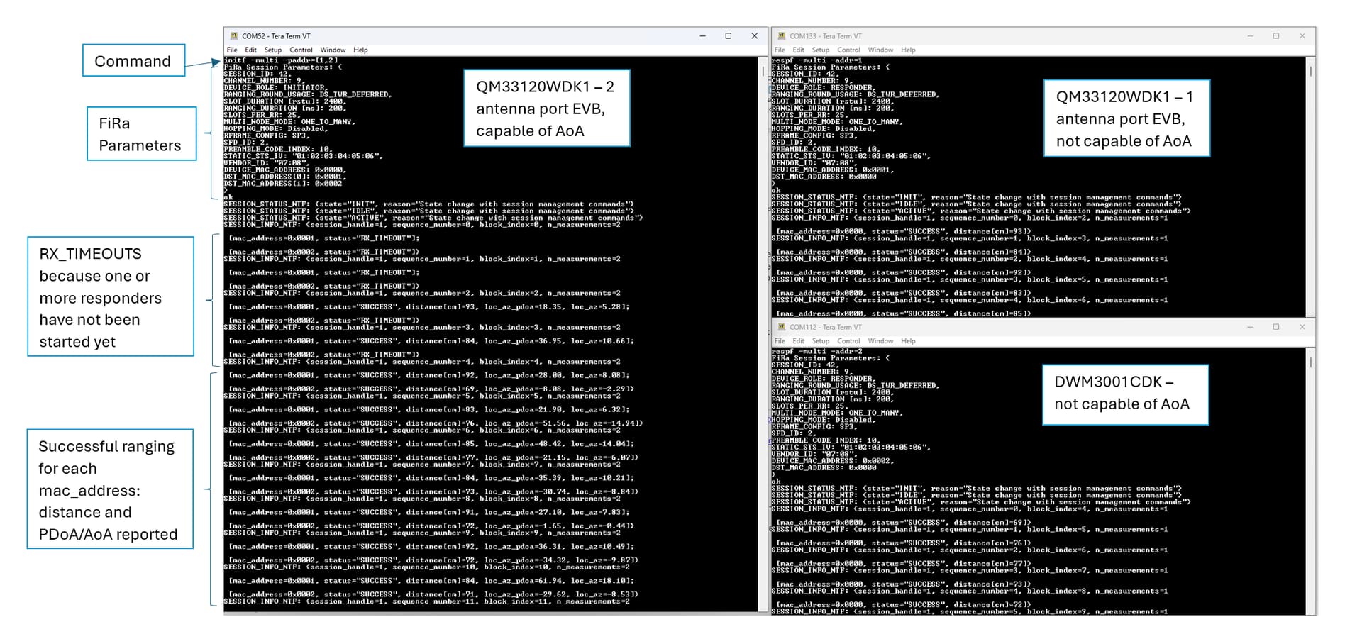
Board 1: initf -multi -paddr=[1,2]
Board 2: respf -multi -addr=1
Board 3: respf -multi -addr=2
Example
The following screenshot involves the use of 3 boards as described above using TeraTerm as the serial port emulator.
Connect each board one at a time to the computer to make sure you are correctly programming and identifying the serial port for each board.
? will give a list of all supported commands in the CLI. help followed by the command will give a brief description of the command and its parameters, e.g., help initf.
Running diag 1 before starting ranging will enable diagnostic mode to enable printing of RSSI and other parameters.
UCI
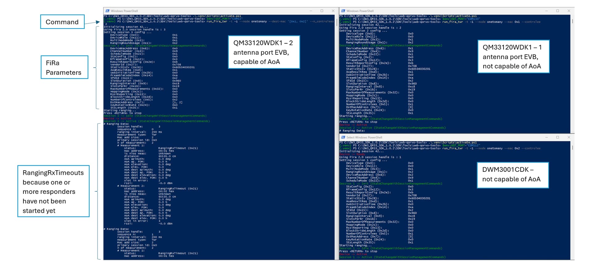
This section how to do O2M ranging with 3 boards using the UWB Command Interface (UCI) application. The UCI application can be run with the QorvoOne GUI (found in SDK\Tools\GUI) or with the UWB Qorvo Tools (UQT, found in SDK\Tools\uwb-qorvo-tools). Here we focus on the UQT method as the GUI method is relatively straightforward.
Flash each board with the corresponding prebuilt UCI example from the SDK. This is found in SDK\Binaries. Refer to the respective Developer Manual found in SDK\Documentation\Developer Manual referring to section 4.4.2 Flashing the development kit.
Follow section 1.2 and 1.3 in UWB-Qorvo-Tools-guide.pdf found in SDK\Tools\uwb-qorvo-tools to setup environment for UQT.
Open a shell that you will use for each board in the uwb-qorvo-tools folder.
In each shell, activate the Python virtual environment (see section 1.3.2 for more details).
In each shell, set the default port corresponding to the serial port of the board you wish to use with that shell (see section 1.4.1 for more details).
Use a release of Python 3.10. The latest release of 3.10 is 3.10.16 found here. We are not supporting newer (or older) versions of Python at this time.
Make sure no other applications are using the serial ports. If you followed the CLI example earlier, the port would be the same so please disconnect the port from your serial terminal.
mode command in Windows PowerShell lists the available serial ports.
-h option with run_fira_twr (i.e., run_fira_twr -h) will print the help for the command including all of the parameters supported.
Closing
If you have a question regarding the tutorial here or you find that there is an issue with the steps, please reply in this thread. We also welcome any suggestions for other tutorial topics for the DW3 QM33 SDK.
Otherwise, please open a new topic with your question and reference this tutorial if needed in your post.
Hello, I have a question about the timing.
If I have one initiator and two responder, and if I set parameters like this:
Block duration: 200ms
Slot duration: 2400rstu (2ms)
Round duration: 25 slots (50ms)
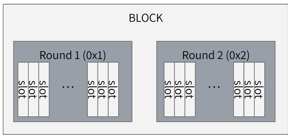
Then, in initiator’s block, there will be two rounds for each responder like this
I wonder about the sequence of each slots.
([ SLOT 1 ] for round 1, [ SLOT 2 ] for round 2)
If the sequence looks like
[ SLOT 1 ][ SLOT 2 ][ SLOT 1 ][ SLOT 2 ] …
then, the two range data in one block are gathered simultaneously.
However, if the sequence looks like
[ SLOT 1 ][ SLOT 1 ][ SLOT 1 ] …[ SLOT 1 ] [ SLOT 2 ][ SLOT 2 ]…[ SLOT 2 ]
└───count: 25 (50ms)────────────┘└────count: 25 (50ms)────┘
then, the two range data has a time gap of 50ms.
I want to make a 2D location estimating system, so I want to get simultaneous ranging result.
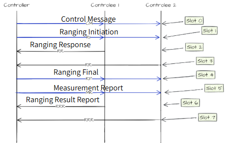
Hi @gochul1995 , if you set up One to Many as described in this forum post, then the initiator will talk to the responders in the same ranging round. After the ranging initiation message from the initiator, each responder will have a chance to respond in the subsequent slots.
More information about this is described in the FiRa specification.
Please open a new forum topic if you have further questions on this.
I have 5 DWM3001CDK module. I Like to use 1 tag + 4 anchors using this module. I tried Following the step you provided. And I do not see “SUCCESS” in tera term as same as yours.I have a few questions.
Do I need to plug the usb cable from J9 to J20 after flashing?
When I configure one of my module as Iniator and responder using Tera term, can I close the tera term, unplug the module to my pc, and proceed to configure other module?
When I finish configuring every module, does the initiator stay connected to my pc? And the responders can power in power bank?
How can I see the ranging?
Sor
Sorry for too many questions. I’m just new to this and still need step by step thank you!
Is there any intention to support 3.10+ at this time (~1 year later)? Any intention for updates to the uwb-qorvo-tools? Public repo tracking?
When you say 8 responders to one session, does that mean you could create many sessions for 8+ responders? Can you help me understand the reason for the 8 per session (I’m guessing its due to FiRa)?
@nlime, the latest SDK mentions support for 3.10 and later. I have not tested it myself but it should be working. Please try and open a new ticket if you experience any issues. At this time, we are not hosting the repo publicly through git due to integration that we have with the Nordic SDK.
Yes, you can create multiple sessions with 8 responders each. You would be limited by the scheduling parameters you select as you would need to ensure that there is sufficient time to time slot in each session. 8 responders is the maximum in one session from FiRa.
The project .toml file that comes with it still says python = ">=3.9 <3.11.0" and if you try to adjust it, I can confirm substantial issues with 3.11+ due to tightening against dynamic enums. The library depends on dynamic enums pretty heavily.
Thanks for clarifying that. Can you ballpark a practical/typical max n?
Hello @akash and thanks for the resources.
I’m working on a project where I need to do Ranging and AoA estimation using a qorvo 3x chip. My question would be if the SDK can be used in any way to achieve this without a seperate MCU additional to the one running my application code. I’m developing ona 3001CDK which includes the Nordic MCU my application code is running on. If I understand correctly I would need a seperate MCU to run the UCI/CLI layer on and the Nrf MCU with the application code would then have to interact with that MCU. Is it somehow possible to do everything on one MCU? Or does that leave me with having to use the raw dw3000 drivers?
Thanks in advance
Depends how big your app is. The 3001cfk running uci doesn’t have a lot of ram space left. Our code wouldn’t fit. I ended up moving to the Murata Type2ab which uses the nRF 52840
Otherwise you will have to use another processor of some sort
Also note that the 3001cdk only has one antenna , so it cannot do aoa. Only distance
And today UCI requires an outside processor to connect to the serial port via USB and run the python scripts to execute ranging operations
CLI could be setup using USB to start automatically on power on, but still reports ranging results on the USB Port.
Everything can be done on 1 MCU such as the nRF52. The CLI example code is meant to show an example for that. Your application should call functions similar to the functions called by the CLI.
The UCI firmware is intended for those who want to interface to a UWBS (UWB Subsystem defined by FiRa). This might be desirable for those who have a more powerful processor to avoid worrying about the realtime control.