Hello.
Is it possible to generate a symbol block with input/output pins directly from a Verilog (.v) file?
When there are many pins, manually setting each pin’s direction is tedious.
Hello.
Is it possible to generate a symbol block with input/output pins directly from a Verilog (.v) file?
When there are many pins, manually setting each pin’s direction is tedious.
If many pins refer to boolean ports, consider to use Bit Vector.
If they are other variable types, use text editor to open .qsch or .qsym for modification is fastest. Here is a study of pin definition in .qsch or .qsym.
Qspice/MDHelp/DLLBlock-AssignPortAndDataType.md at main · KSKelvin-Github/Qspice
Step 1: Use text editor[1] to open .qsch or .qsym with Ø-Device
Step 2: Pin is described as «pin (-2300,1000) (0,0) 0.926 7 17 0x0 -1 “InputBoolean”»
| Item | Description |
|---|---|
| (-2300,1000) | pin position |
| (0,0) | pin label position offset |
| 0.926 | font size |
| 7 | pin label justification |
17 |
port and data Type |
| 0x0 | |
| -1 | |
| “InputBoolean” | pin label |
Step 3: Modify port and data type (17) with text editor by referring to table below
17 by 146| Data Type | Port : Input | Port : Output | Port : DLL’s GND |
|---|---|---|---|
| 1 | 2 | 3 | |
| Boolean | 17 | 18 | |
| Char | 33 | 34 | |
| Unsigned Char | 49 | 50 | |
| Short | 65 | 66 | |
| Unsigned Short | 81 | 82 | |
| Integer | 97 | 98 | |
| Unsigned Integer | 113 | 114 | |
| Short Float32 | 129 | 130 | |
| Float | 145 | 146 | |
| Integer64 | 161 | 162 | |
| Unsigned Integer 64 | 177 | 178 |
Text Editor : Notepad++ : https://notepad-plus-plus.org/ ↩︎
Is there a comprehensive guide somewhere of what is each type of output?
like in C++ i can imagine float is analog output, but in verilog i am not so sure.
Maybe output digital and then use a large low resistance divider by 100 or something like that?
Good question, to be fair i did struggle at first and only made it work after i asked here.
here this might help, i cant get C++ to run but i sort of made Verilog work somehow.
You can consider to read the Qspice help, and may be my device guideline, Ø-Device section.
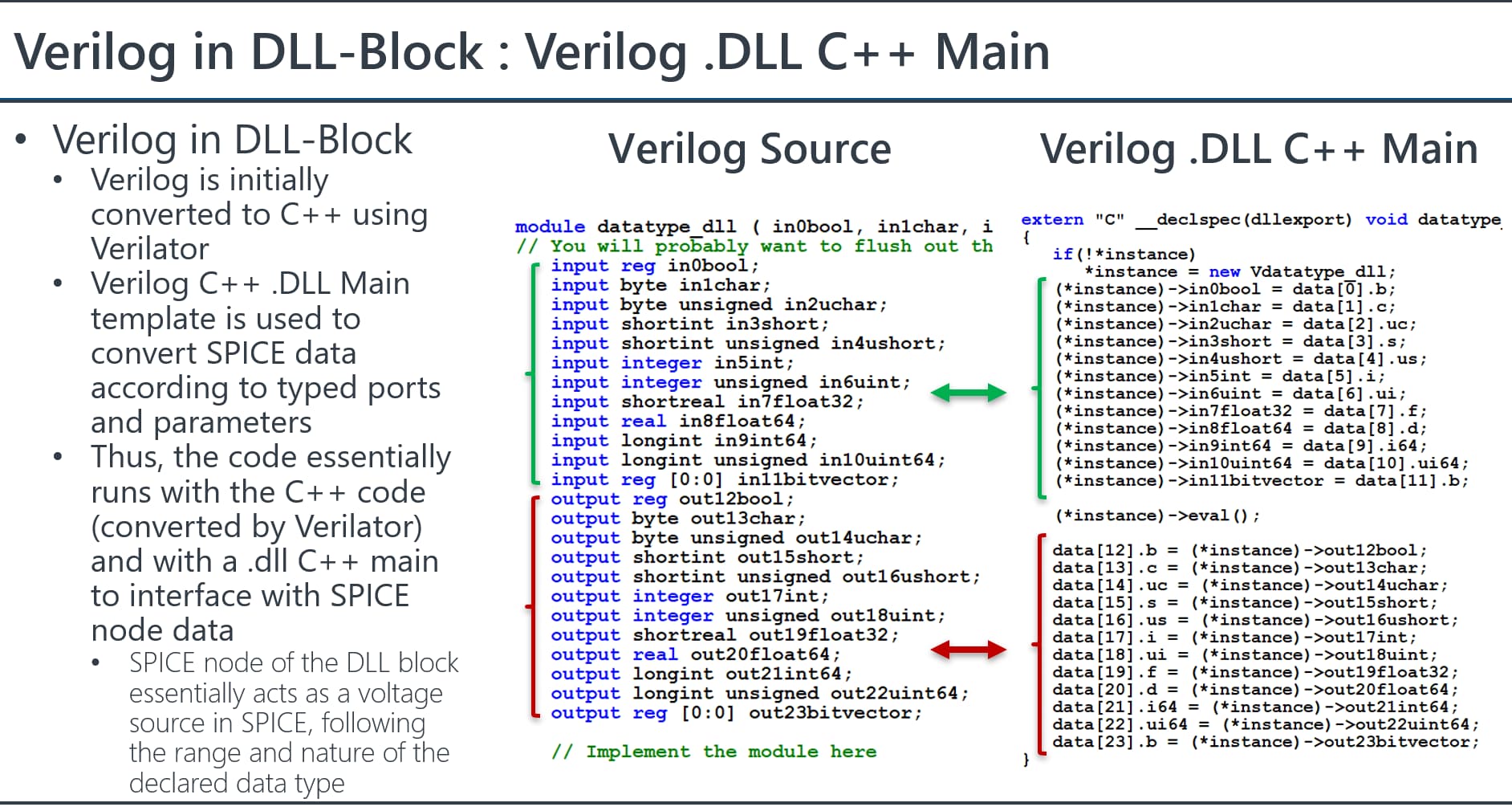
Basically, C++ or Verilog both compile to a .DLL file to execute with QSPICE. Verilog is converted into C++ through Verilator (this is mentioned in the footnote of Qspice Help - Ø-Device). For Verilog, Qspice needs a Verilog .DLL C++ main template to bridge the data type between C++ and Verilog. This Verilog .DLL C++ main template is auto generated by Qspice, and not need to be edit. (If ports change, need re-generate a new one).
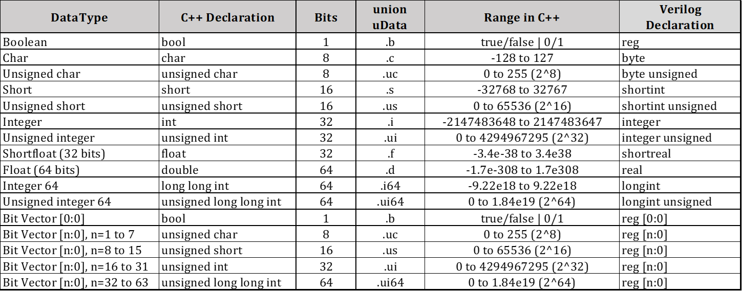
Data type defined in C++ have equivalent data type in Verilog. Now, it actually no different for Ø-Device interact in circuit simulation with language written by C++ or Verilog.
Output ports of Ø-Device are basically voltage sources with Rout and Cout (their value can be changed in instance parameters). An integer is a limited range voltage source with only discrete level of voltage, a float is voltage output with floating point, a boolean is voltage output between VHIGH (default 1V) or 0V.
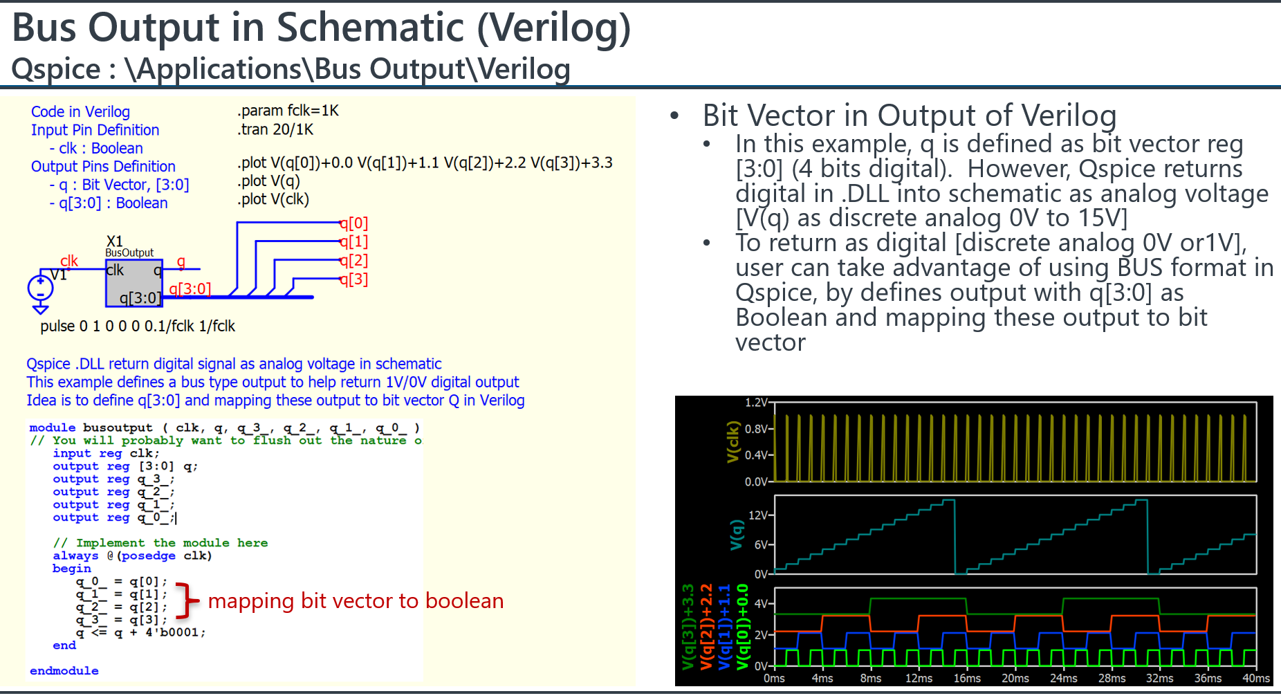
I don’t work with Verilog, but I believe that generally, Verilog works with the data type “reg” which represents values of 0 and 1. The output ports typically act as voltage sources, outputting either 0V or 1V (or following the instance parameter VHIGH).
I assume that declaring inputs and outputs with Bit Vectors might be easier. However, as I mentioned, I am not experienced in Verilog, so there is a possibility that I could be mistaken.
Here is an example I setup output with bit vector (q), and also setup one with BUS format (q[3:0]), such that I can get the digital pattern or analog discrete voltage.
Parent.BusOutput.qsch (2.0 MB)
busoutput.v (505 Bytes)
This is great resource.
Also i would suggest that in the Data Type column you also make it a bit more clear that you also need to set the port to that data type.
Also as a side note what would be the use case for CHAR data in Qspice? only thing i can think off is I2C or SPI commands to a emulated IC.
I agree great resource.