I am a long time user, with application on switching converter simulation.
My question is, how to make sense of where to add some rser or small caps across the circuit to aid the convergence and overall runtime speed?
My schematic is primarily consisted of one or a few Cblocks and ideal switches and diode, I have faced multiple simulation where the sim randomly throw timestep too small.
My common approach is to place rser=1m at almost all components and add a few 1pF capacitor at some switching nodes. Generally, this method improve the convergence. But, sometimes adding or removing a single rser can change the sim time by 3x.
Your approach is good. The next step is to increase / decrease the value of the added capacitors or resistors (or use the proper .options for that). If these fail, check the quality of any subcircuit or .model statement.
This should result in a working simulation but not necessarily a fast one. You may want to explore the option of a piece-wise linear simulator (i.e. using ideal components and no device models).
I always use voltage controlled ideal switch and ideal diode (with behavioral model) in Qspice to have as close to ideal as possible, and as fast as possible runtime. But yeah, the some unpredictable timestep too small can be cumbersome from time to time.
Anyway, I do have access for PSIM and Simulink+Simscape electronics licences in my employer.
However, the fact that:
every sim parameter is laid bare on the sch (makes the sch very intuitive to understand)
the most powerful C-block on any circuit simulator.
the .step parameter sweep is bueno…
I actually much prefer to wait a bit longer to get the sim done since I can do the actual development faster.
Are you using the MaxExtTimeStep() or Trunc() functions in your C-blocks? If not, the timestep is dictated by the other circuit elements. The timestep value at each computed time interval uses the smallest “requested” timestep from all the components.
Another suggestion: Are you using the .options MAXSTEP=‘x’ as a directive? Try a larger value. Lower it if you’re not getting the timing resolution you need.
Another way I found to reduce sim time is to use the .save directive. By specifying ONLY the data you want to collect in the .qraw file, you reduce the time it takes to load circuit data into this file. It still uses the same number of timesteps but with less file appends.
I have other tricks but they might not apply in your situation.
What percentage of your sim is analog? If you’re using a highly digital-based sim, there may be more tricks to reduce sim-time.
I am using MaxExtTimestep to compute the digital PWM transition time (0 to 1 or 1 to 0) for digital PWM…its the fastest method you can have for PWM generation…
I have also used .save to specify the data I want to save. Additionally we can also use CULLTIME to down sample the stored data thus you can eliminate the excessive data stored during heavy nonlinearity from very small timestep.
My sim is largely for high power electronic design. 3phase inverter (2 level, T-type, ANPC), totem pole PFC/inverter, 3phase LLC, DAB… all with digital controller simulated in detail. Not sure how you may categorize it as digital or analog…
I figured you were using many of the tricks I mentioned since you are a long-time expert user.
Here is what I learned about how QSpice is computing the next timestep from my own experiments and from @KSKelvin. This might get long-winded…
The next timestep to use is the smallest value requested by any component in the circuit. The next timestep after that will basically increase to double the previous value unless a component requests smaller value. If a component requests a 1us timestep, the next timestep is 2us. The next timestep afterward is 4us … etc. My question about the analog components is that you might be stuck with a small timestep value if these are asking for this value. If you’re using L or C components, I have found no good way to increase the timestep aside from specifying a larger R value to lengthen the RC or RL time constant.
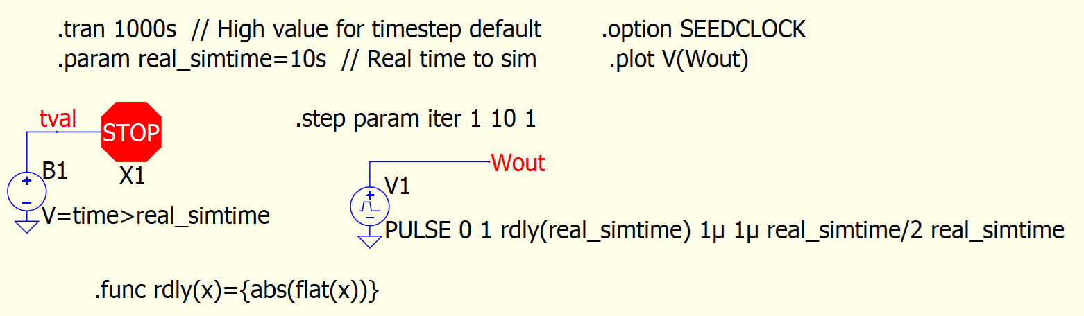
The default Max timestep for a .tran without a .options MaxStep setting is computed by the maximum sim time from the .tran directive divided by 1000. Therefore, if the max time being sim’d is 100ms, then the default MAXSTEP= (100x10^-3)/(1x10^3) => 100x10-6 = 0.1ms. This computed MAXSTEP overrides a .option MAXSTEP directive. Trick: Set the maximum time to simulate to some large value (ie. 1000s). Then use the stop or abort feature in QSpice to stop the simulation time earlier.
Stop_Sim_Time.qsch (3.4 KB)
Notice the max timestep intervals can get closer to 1s.
Now set .tran to 10s. You’ll notice the max timestep is close to 10m. Ie. 100x more timesteps and resultant data. Now add the .option MAXSTEP=1s. No improvements. This default directive is ignored.
I tend to run sims that are multi-stepped and are mostly digital with a number of C-blocks. As a consequence, I have run sims that take DAYS to complete. Can you imagine the .qraw file being generated? Even reducing the number of data points to save using .save still doesn’t work.
Therefore, I run my sims in a batch file and turn off the .qraw generation. This works for me because I’m running a statistical digital analysis where I’m determining that completion of a specific task. I use a C-block I created to log the specific data I want to a .csv file for later analysis. Here’s a link to the logger C-block: New Component: Logger V2.2 [IMPORTANT UPDATE].
By eliminating the .qraw output and the QSpice GUIs, I have save significant time to complete the simulation. Some of the sims still takes days but I have noticed a reduction of at least 2x the time.
I realize this trick may not work for you.
There may be other tricks that others might contribute.
Hopefully this elaborate explanation might help and bring some insights to improve your sim times.
I bet the last effort I can do is to use the batch mode (though, honestly I don’t really prefer to do this).
I have developed FRA measurement since I started with Qspice, and I did it without storing any .qraw data, just do everything in Cblock, and export the result to small .csv…and the reason was exactly that built in FRA is done in post processing which is bloody slow for long transient sim.
The long Tstop isn’t actually working for, since my switching period is almost always <Tstop/1000
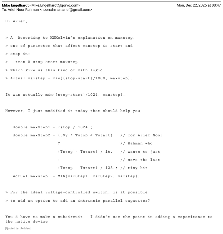
Anyway, I have confirmed with Mike recently on maxstep in relation to Tstop, then he was kindly modify it to cater for my need
OK, the original post wasn’t specifically about making C-Block code fast but the topic has come up. I can think of many ways that a DLL component might run slowly and thought that I might work up a document on the topic (too much to brain-dump here).
So, does anyone have a project that seems computationally bound by a DLL? Would you be willing to share it to see if it can be improved and, if so, we can all learn from it?
One step I find recently to be able to run SMPS / digital PWM quickly and reliability are:
run simulation without any extra .opt
change solver by add .opt method=gear
add .opt cshunt=.1p and/or add .opt gshunt=1p to add small impedance (C or R) from every nodes to ground and/orr add .opt reltol=.1m to tighten overall simulation accuracy.
→ choose some permutation of these 3 .opt (generally I prefer to use cshunt first, then add gshunt or just use gshunt, or can be just use reltol… unfortunately there is no single fool proof solution).
do it methodically, from step 1, if timestep too small occurs, then continue to add the steps 2 3 4 one step at a time.
anyway, I find that doing these steps are more reliable and faster than using 80-bit solver (.opt fastmath=false)
Specifically for @RDunn , perhaps you can share your particular use case. In my own case, I also only use C-block for my controller… my trick for speeding up is basically to not any native block (or minimize as much as possible) for control purpose (particularly for PWM generation).
@physicboy The way you are using SPICE simulation is quite unique; I suppose not many people work in this manner. Very few engineers are capable of working in digital + power electronics + simulation. Possibly, you are walking alone on this path.
We all know that SPICE is not designed to handle an ideal switch (the I-V curve almost a 90-degree change). Possibly Mike is the first one to allow a nearly ideal device to work in the SPICE platform. As you are younger than me and did not go through Microsim → Pspice → LTspice → Qspice. If you went through this path, you possibly are not thinking about the simulation speed, as you cannot imagine how slow it was when simulating back in the old days. My struggle was always with the timestep being too small, not the simulation speed.
Just out of curiosity, what are the Ron and Roff values of your ideal switch and ideal diode?
@KSKelvin , I hope you are wrong on the first part…
You are not that much older… haha, I started with PSIM back in 2011 for undergrad project, then PLECS for a short year, then directly Qspice (I knew LTspice, but cant understand very well… luckily I joined Qspice band wagon from the very start and it helps a lot by knowing the development history).
Anyway, actually my problem is similar with you… I only start to add some .opt as I start having timestep too small problem or I notice suddenly the sim become very slow after I modify the circuit. But, I often took a poor choice and the sim work but extremely slow.
Typically I choose:
.model SA SW ron=1m roff=10E6 vt=0.5 vh=0
.model DA D vfwd=4 ron=1m roff=10E6
→ sometimes can be 4V to simulate SiC body diode or 1V to simulate common power diode.
Your switch and diode are reasonable. I believe you currently working on 3-phase systems and many switches in your simulation, that make thing much harder than normal. I started SPICE in power electronics back in 2001, so, definitely older.
SPICE is not a fixed step simulation; in contrast, its convergence is a combination of two aspects. Each timestep involves solving a DC operating point using the Newton-Raphson method, and if convergence fails, it reduces the timestep and repeats the process for transient analysis. However, to be honest, I am not completely sure if what I am talking about is exactly how it works. As a result, it seems there is no definite way to determine how to generally optimize a circuit for both convergence, accuracy, and simulation speed. Engineers working in their field come up with their own experiences to address their needs.
Before Qspice, there was no integration of digital (C++ or Verilog) into SPICE; therefore, what you are working on is a completely new area! It is very interesting that even though Qspice has been launched for two years, many engineers are still using LTspice. Some of them simply don’t like the Qspice interface, or not in Linux, or library is still limited, while others may not have experience with programming, making this unique feature less appealing to them. (Tell me, how many engineers have you met in your career who can work in both hardware and software (embedded system)?). I might have slightly digressed from the main topic.
My point is, ultimately, you are the engineer in the community who helps and suggests to others how they can adjust the simulation parameters to make their simulations work efficiently. Most likely, what you are dealing with is an area of expertise and experience.
yes… my circuit easily have 10+ switches and 10+diodes… solving with realistic diode kills the simulation.
The use of C-block is the biggest reason why I get down to the rabbit whole of Qspice, without it I wont touch Qspice honestly. But you are right, its already very rare to find hardware guys who do proper simulation and even only a fraction of those can do actual C-code. So, what I find very appealing in Qspice is not what majority of people considered to be a selling point.
I guess at the end you are right… we are going to go to our own niche and just try to be very good in our own playing field… for someone of your deep knowledge, whatever question that you have you are the person who will answer it at the end…
FYI, yesterday’s release included: “01/04/2026 The Digital Mars compiler is now encouraged to do more optimization.”
In theory, your DLL code should run faster after you recompile. I doubt that it will make significant improvements but, if you notice changes (good or bad), please share your experience.
PLECS and SIMPLIS are designed for power electronics and the simulation speed is faster than SPICE-like simulator.
But QSpice is more portable and support C-Block like PLECS, more importantly QSpice is totally free and updated all the time for a better and easy-to-use simulator.
By the way, I also use QSpice for digital control SMPS with exmples that you proivde. Thanks much!
It is my understanding that there are two basic elements that account for long sim times:
The number of timesteps to reach the final result.
The time to compute for each component at a time value.
I wonder if it makes sense to determine which of the above is true (or what percentage of both is the biggest contributor.
The number of timesteps may be highly dependent on the accuracy you need at small time intervals. Allowing for larger timesteps may shorten the sim time at the potential sacrifice of accuracy.
C-blocks allow for requesting larger (or smaller) next timestep values. Highly digital C-blocks can request larger timestep values since it can predict state changes.
Mike’s implementation of estimating the next timestep on analog components appear to use a “doubling” method probably to reasonably simulate exponential events.
I think that I’d say it differently. The total time depends on the number of circuit state calculations. A single time-step may require multiple circuit state calculations. So the number of time-points in the simulation results may not directly relate to the number of circuit calculations.
For C-Block components, Trunc() may reduce the step causing not only a recalculation for the current time-point but also additional steps as the time-step doubles back to the nominal “time-step.”
Technically, a C-Block component cannot increase the next time-step that QSpice will take, it can only request a smaller time-step.
You are correct. My statement was “requesting larger (or smaller) next timesteps”. What I didn’t qualify was that the “shortest straw (timestep)” in the circuit wins. Having a C-block request the largest timestep they need potentially reduces sim time. This is accomplished using the MaxExtStepSize() or Trunc() functions.
This is the reason, if possible, that I prefer to use MaxExtStepSize() instead of Trunc(). MaxExtStepSize() doesn’t allow reverse stepping of the time value.