Something seems to be off with these analog built-in models. Either I am missing something important, or these models are simply wrong. Maybe the models are good enough for limited and simplistic academic use, but in real applications most certainly would lead to catastrophic failures. Any help would be appreciated.
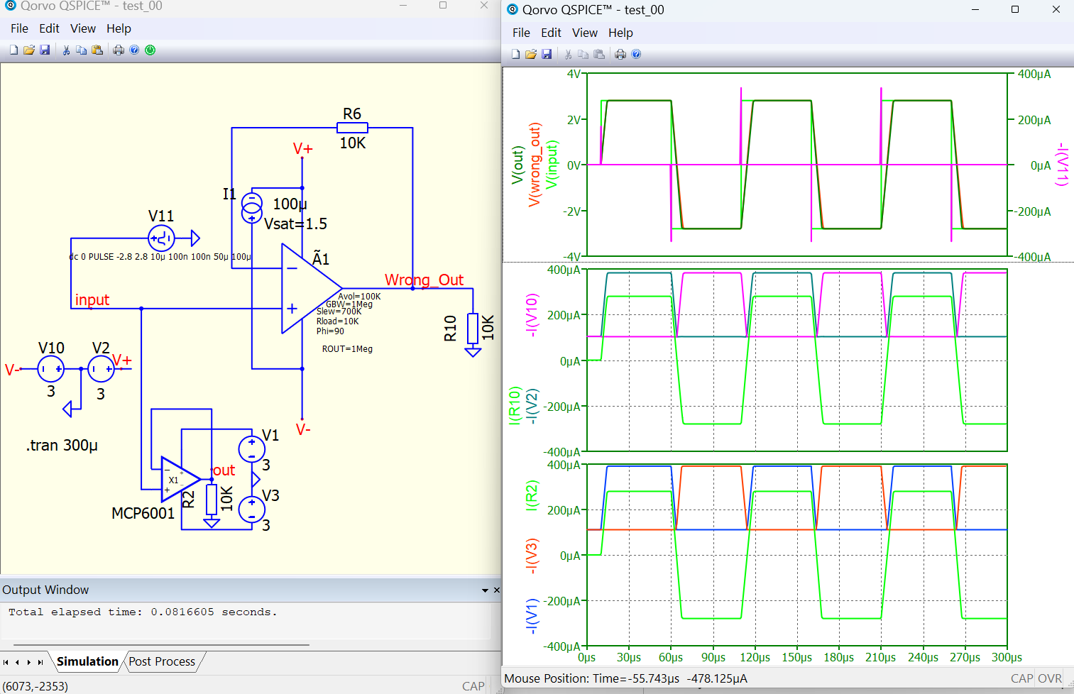
The test example with a Generic Rail-to-Rail Output Op Amp is attached here. One very weird observation: the output exhibits gigantic voltage spikes, higher than the power rail levels, like somebody added inside the model a spiky voltage generator. Even more, this internal voltage generator produces output voltage spikes in anti-phase with the output.
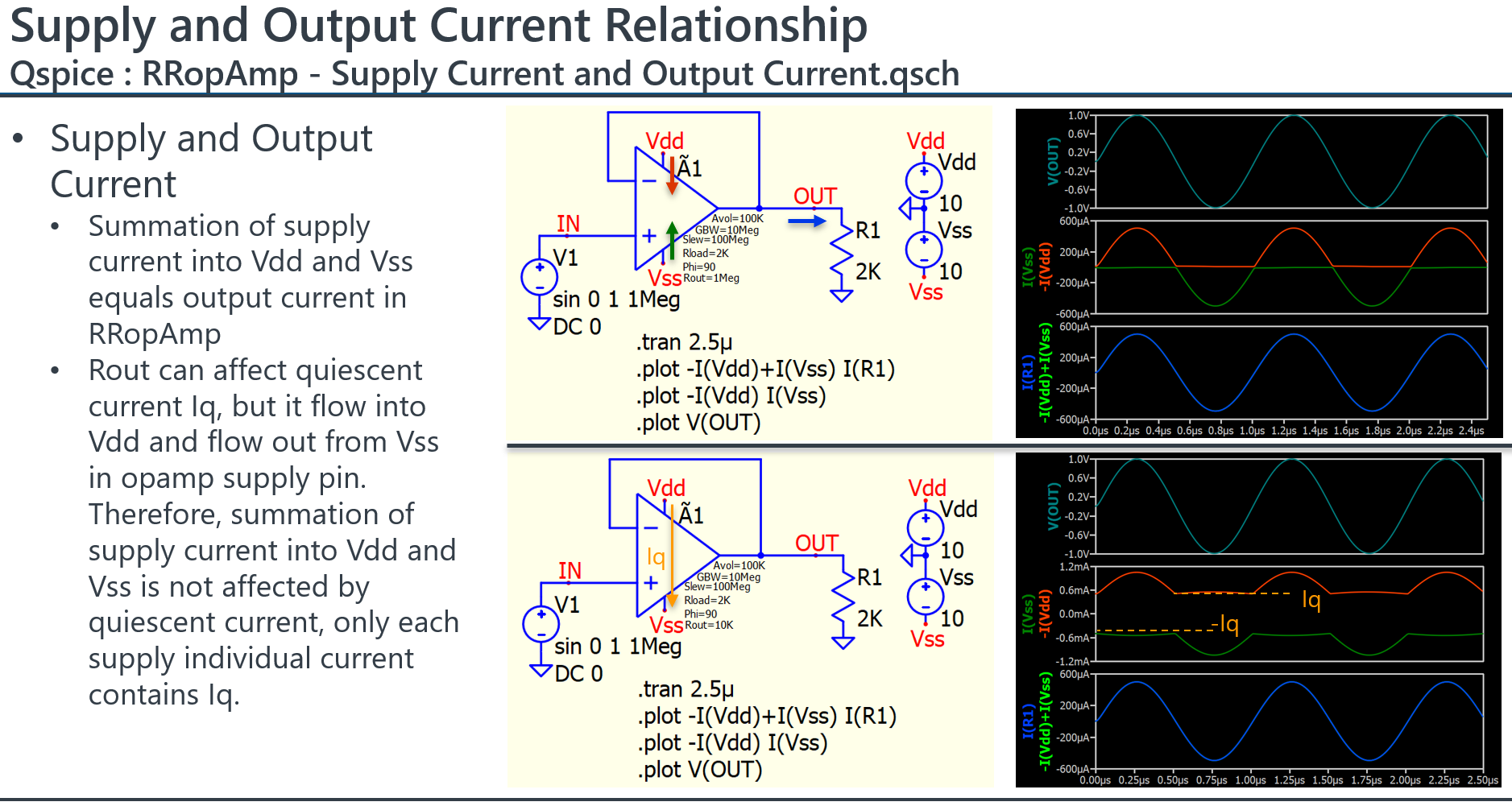
Another weird issue, the currents from both voltage rails V+ and V- are absolutely off the chart, a few orders of magnitude higher than the real case, and kind of random. These power rail currents are not related in any way to the current provided by the Opamp to the output.
Probably the model with reference to zero GND (not a floating reference) can fool a freshman thinking the model works just fine. Unfortunately, it could end the career of that poor guy if he tries to use it for real work, it can blow up an expensive product.
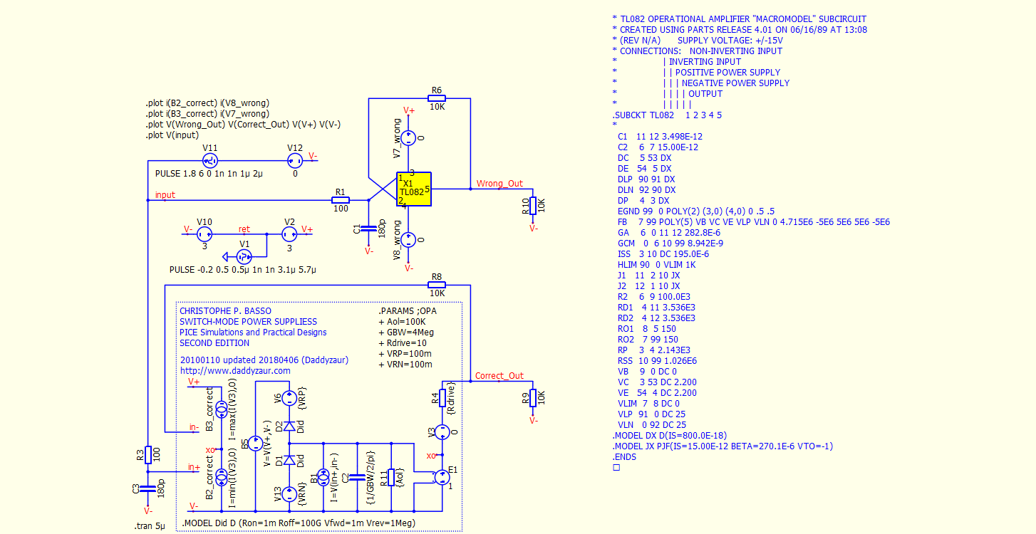
When you change to some real opamp , like TL082 the simulation result is similar (supply current). Same result you get in LTspice. Except that SR of TL082 is like 10 V/us.
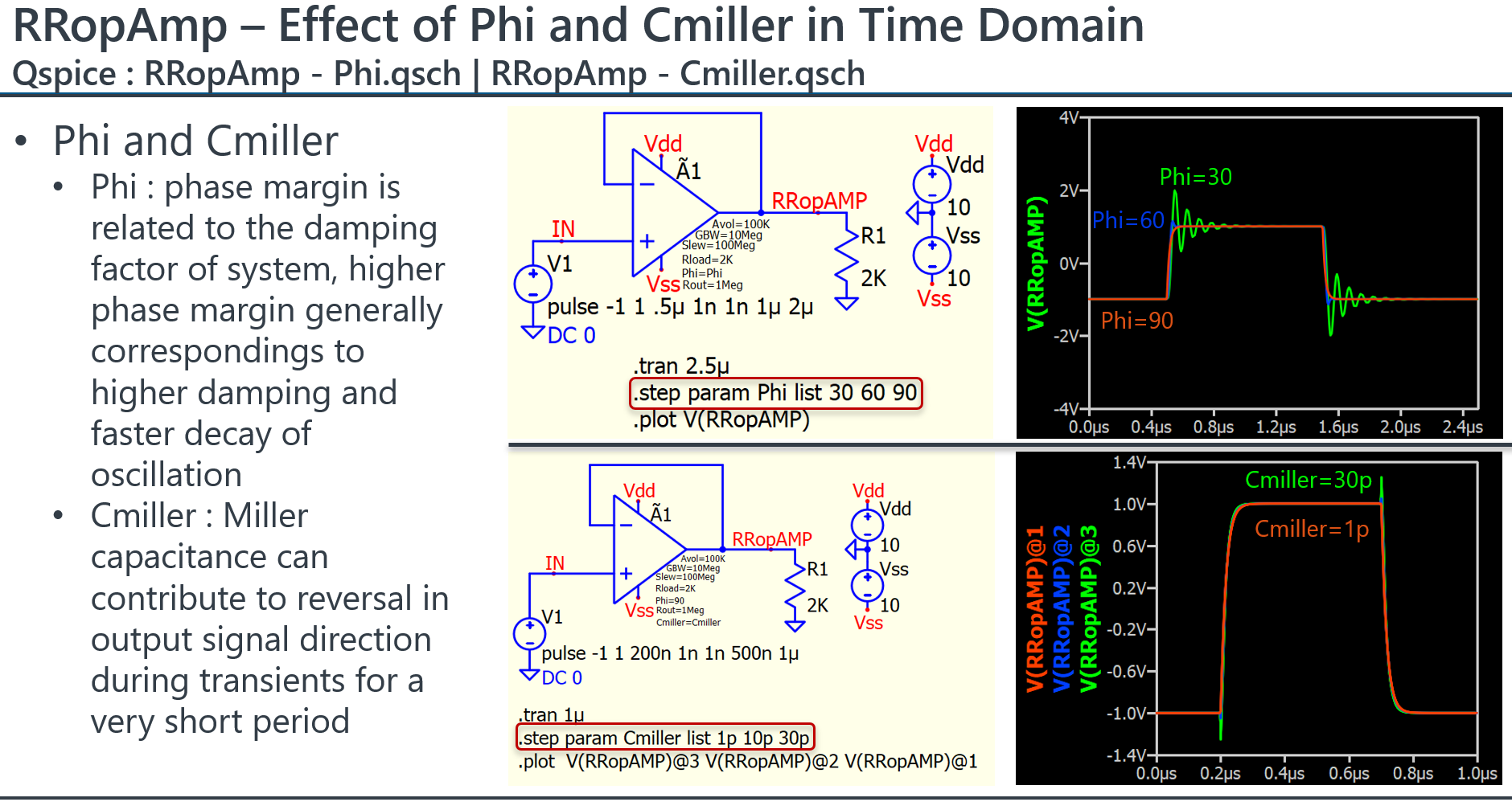
If you want to remove spikes from output you need to set phi to 90°.
Thanks Ivan. The issue is not with manufacturer models that maybe would work or not. The issue is with the “ideal” QSPICE model that is supposed to always work at maximum simulation speed and absolute precision, much better than any other model. It is supposed to be IDEAL and help to quickly identify otherwise impossible circuit problems; unfortunately, is just not working. Even worse, if this default ideal model is used in some other, more complex QSPICE proprietary models or some user circuits, then the whole effort to design/analise a product will turn into an expensive failure.
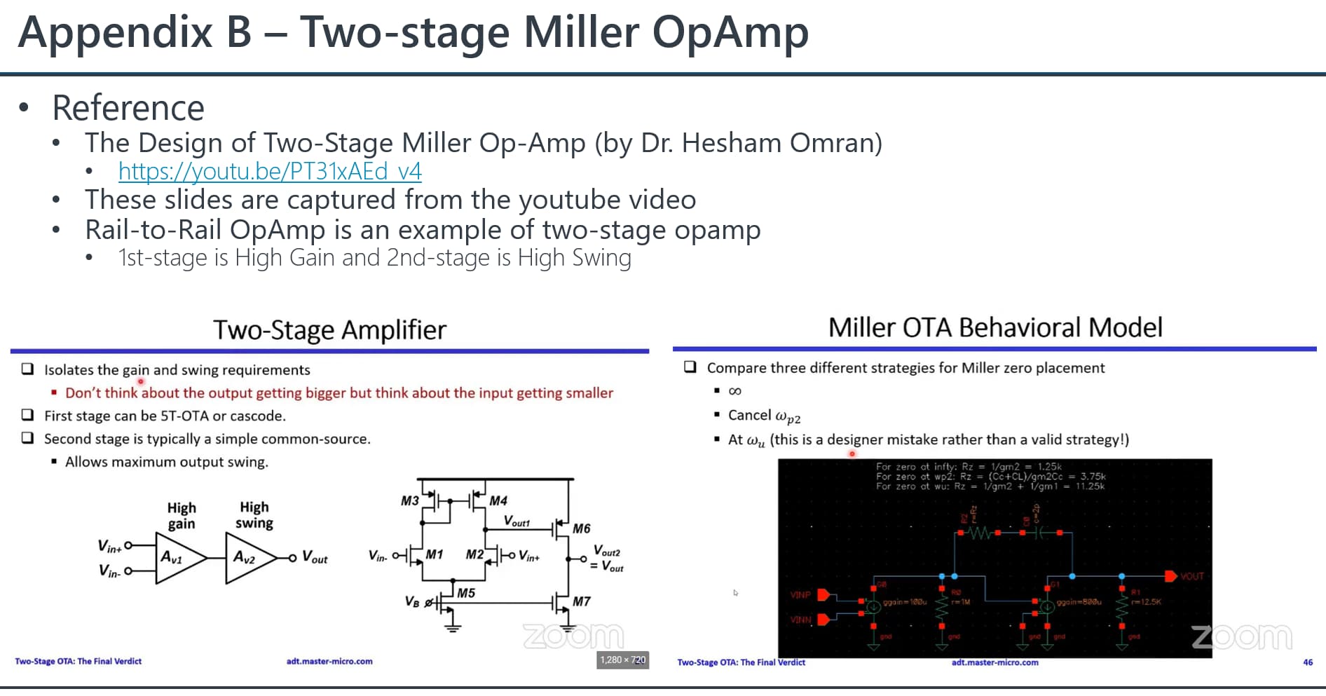
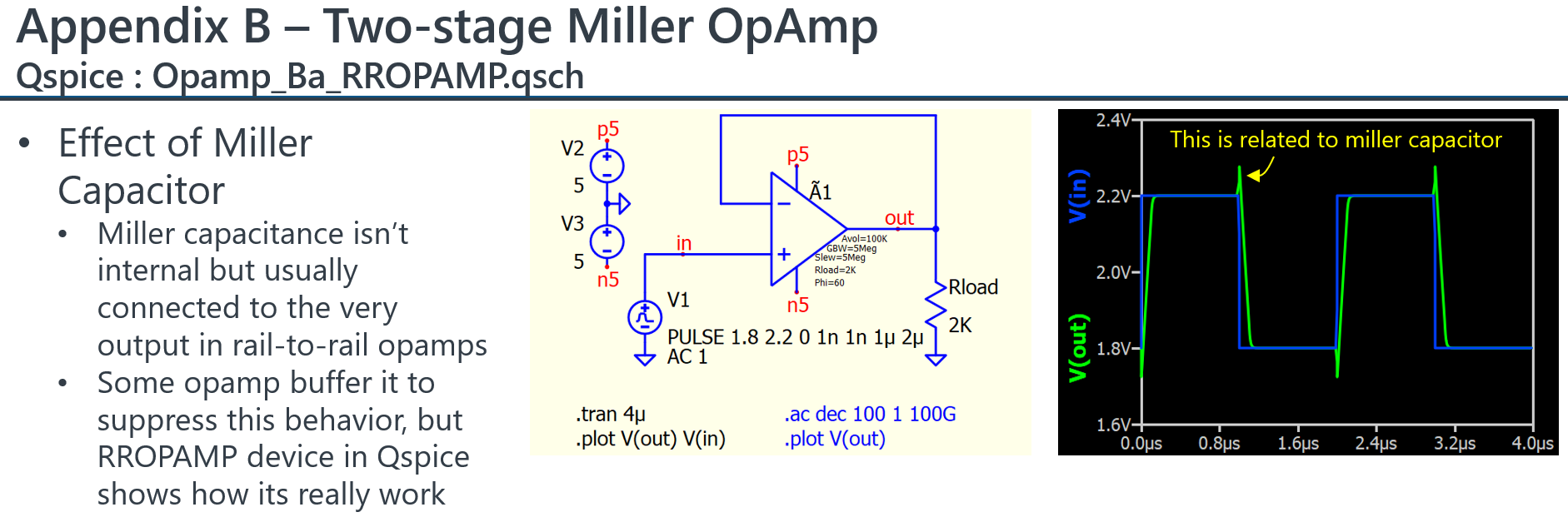
RRopAmp is not an ideal model, it is used to model Rail-to-Rail output opamp. This is a characteristic which confirmed from Mike, by the miller capacitance that connected between input to the very output. Some opamps buffer it to suppress that behavior. This RRopAmp also not model older style opamps that aren’t rail-to-rail, but have complementary emitter follower outputs.
My impression is that, this device is basically like the A-device in LTspice, which is a building block for manufacturer to build their complex opamp model. In general, RRopAmp can work in simulation as a general opamp. If it not meet the expectation, ideal opamp with E-source, or single pole opamp from LTspice can be considered as Ideal. Or just like your case, to build your own opamp model.
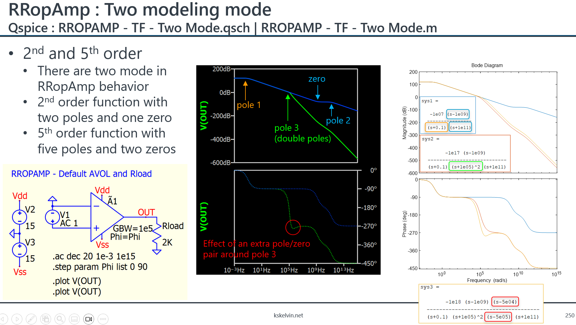
Transfer function of RRopAmp has two poles and one zeros, and your model is single pole. First-order system always well damped. There is no value for comparing with RRopAmp, as it is just a different thing.
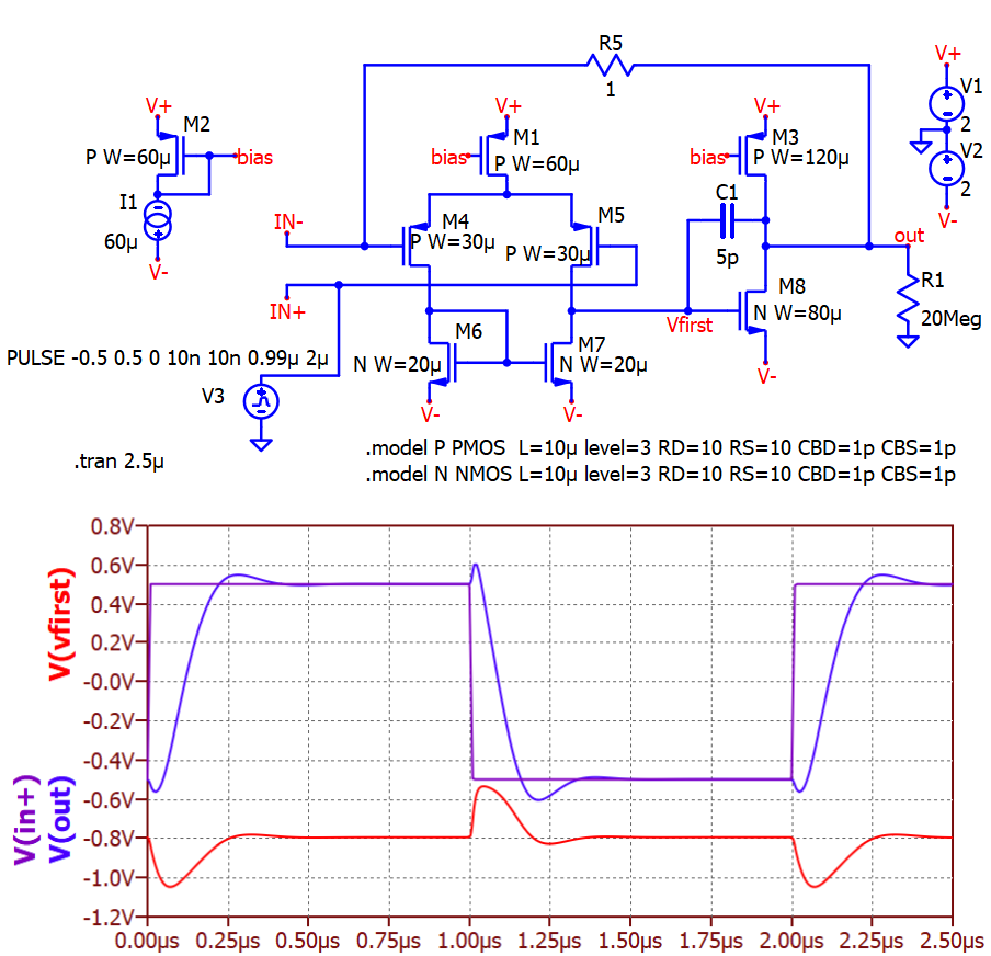
Here is miller study I performed for your reference.
Correct me if I am wrong, the spike you see going up just before the output voltage goes down is not related in any way to any parasitic capacitance. The miller capacitance is real and is degrading the speed of the opamp since has to be charged/discharged, but it never generates this kind of voltage spikes. Or, in other words, have you ever seen an output of an opamp going significantly higher, over the input voltage rails, just before going down? And what about the current through the power rails, is in any way related to the output current (with floating GND)?
The Miller effect is real and there are references available on the internet, such as the youtube video I included in the slide I attached. Op-amp manufacturers seem to have found ways to suppress this effect. As you know, an op-amp is expected to be much more complex than what can be covered by just a single device.
But I am not an expert in op-amps; some of your questions require someone else to answer. Since Mike confirmed that this is an intended characteristic, I trust his word as he is an expert.
Recent updates, 15–16 August 2024, resolved the behaviours that surprised the original poster:
supply-current spikes during sharp transitions
reverse-direction spikes in the output at the beginning of transitions.
It looks to me like the power supply is no longer bridged by 2×R_out, reducing quiescent current.
The help-file now lists the defaut values of the parameters of RROPAMP.
There are a few related items in the Revision History around 08/16/2024 (mm/dd/yyyy).
I do agree that those behaviours were plausibly realistic, as pointed out above (just maybe surprising in a generic op-amp with default settings) :
Supply current can spike during quick transitions in a push-pull output stage, depending on the timing of the push and pull, and what capacitances have to be charged to change state.
The TLV9101 datasheet shows small reverse-direction steps in its small-signal output. A simple MOSFET implementation can show these reverse-direction steps—if I use an unnecessarily large compensation capacitor (sometimes called ‘Miller capacitance’ in this context, but not a parasitic) with no series resistor. There are two negative-gain stages here, and C1 can pass transients in the first stage output to the final output.
In the discussion, Mike decided to rework the RRO op-amp to reduce the quiescent current and to have the gain-bandwidth product (GBW), phase margin, Miller capacitance, and midband voltage follower output impedance to be independently adjustable, and to include their default values in the HELP section. I think this is what several of our community members are looking for.
@OHara , probably you stumble on one of the answers, related to some weird spikes. Not sure if the standard model was updated or not by now (I have seen some taking about updates). Looks like instead of the minute energy stored in a puny Miller capacitance the model was pushing many orders of magnitude higher output currents, something like a Miller supercapacitors. In your example with 5 pF in a 20 Meg resistor yes, you will see a bit of a spike. Replace that with a realistic load, something like 10 k for example, plus some capacitive output load, and double check the same.
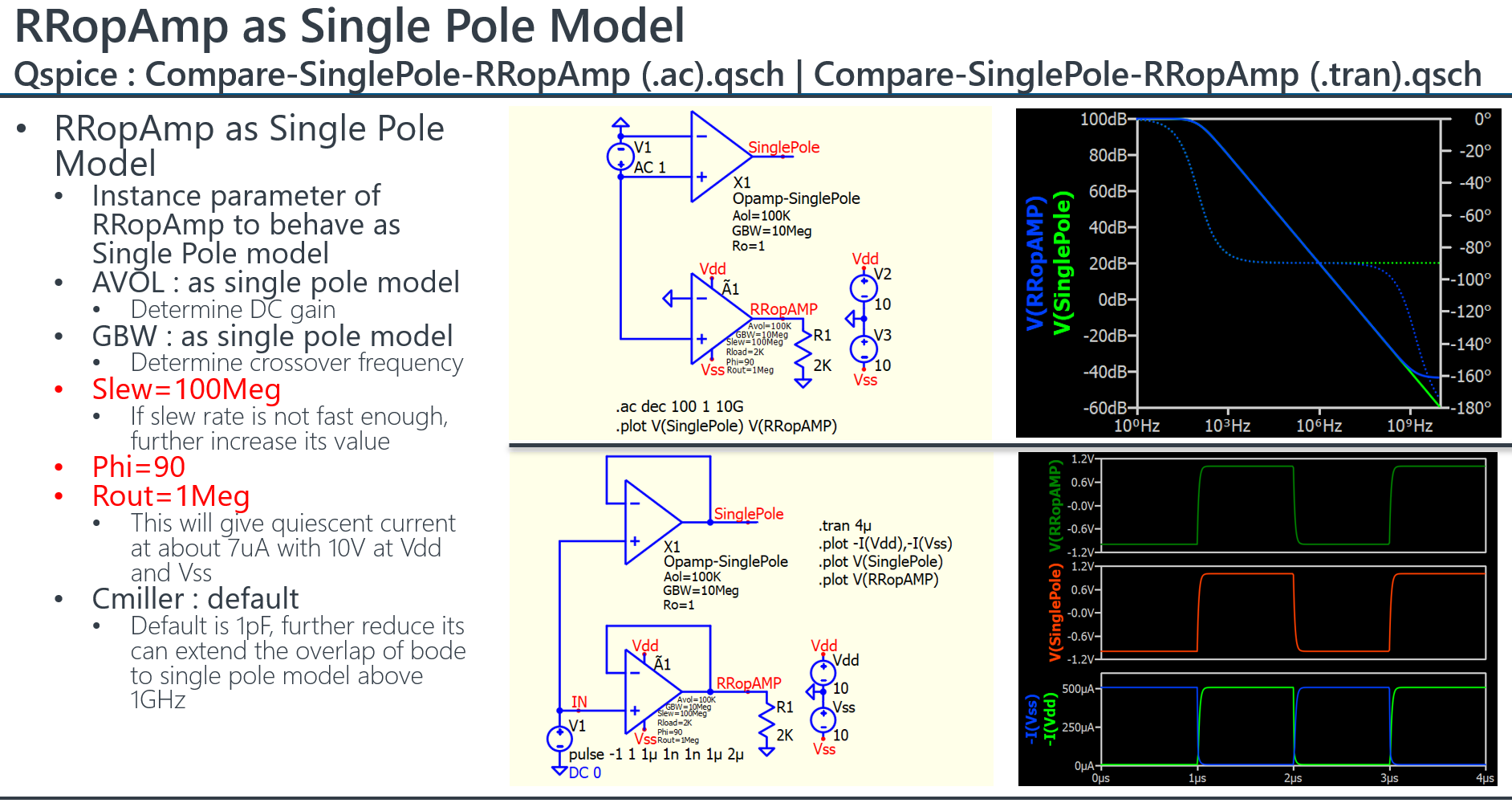
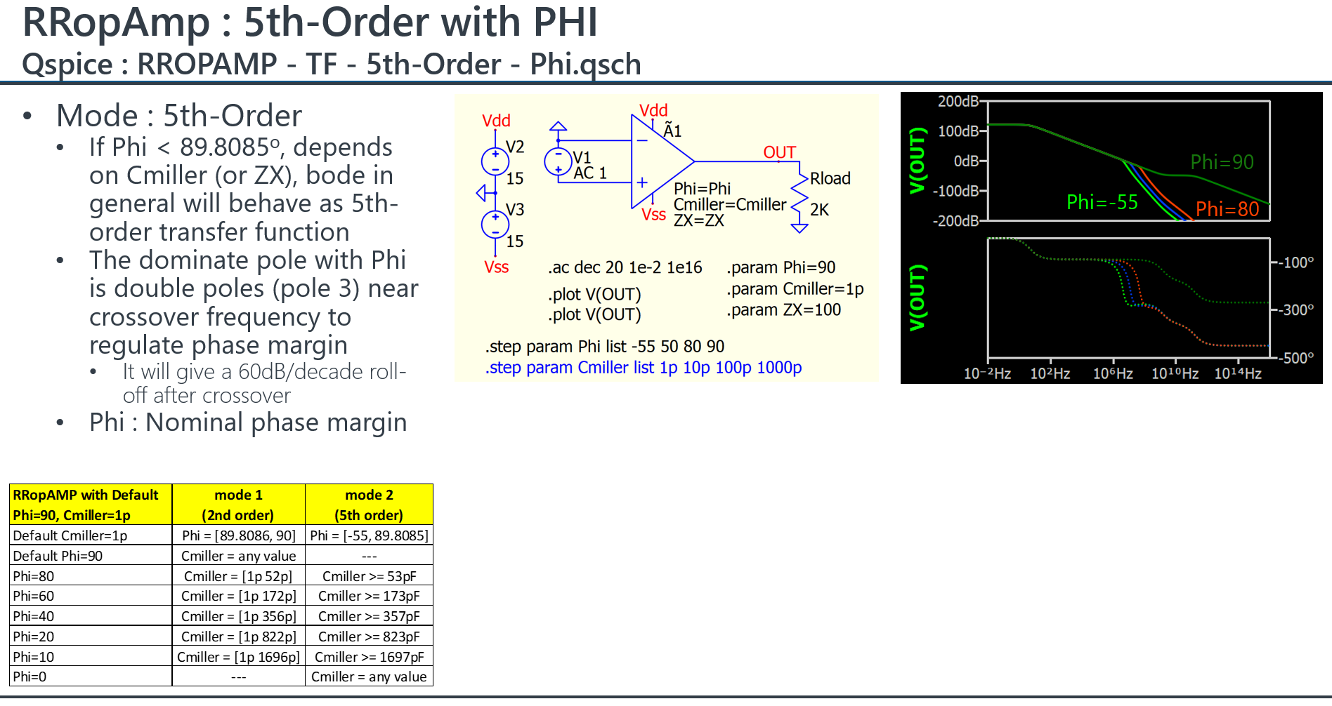
This is a quick overview of RRopAmp after Mike’s rework on August 18, 2024.
Since this post begins with a comparison of RRopAmp to a single-pole model, the instance parameters of RRopAmp need different values to force it to behave like a single-pole model (the default RRopAmp will behave differently). The key is to set Phi=90. Increase the slew rate as in the ideal model without a slew rate limit, and if a very small quiescent current is needed, increase Rout.
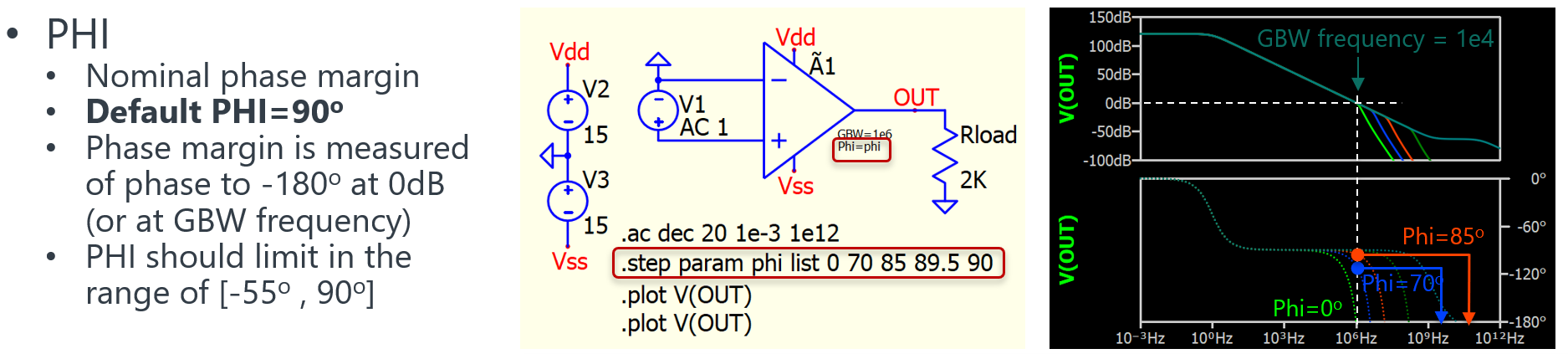
And finally, provide a slide to demonstrate the use of phase margin and Cmiller. Currently, we can expect much more flexibility in using the RRopAmp for modeling a rail-to-rail op-amp, as Miller and phase margin can now be independently controlled.
I was wrong above, about Rout no longer bridging the supply terminals. The “RR OpAmp” models a quiescent current draw as if there was a resistor value 2×Rout from the output to each of the supply rails.
A simpler way to make a generic first-order op-amp is with the ‘MULTGMAMP’ Ã device, loaded with an R and C. These loads can be implemented in the device itself with the parameters CAPVDD CAPVSS and ROUT.
The only advantages, though, over a textbook small-signal model using the simpler G device, are if you want Qspice to simulate the power-rail limits and/or amplifier noise.
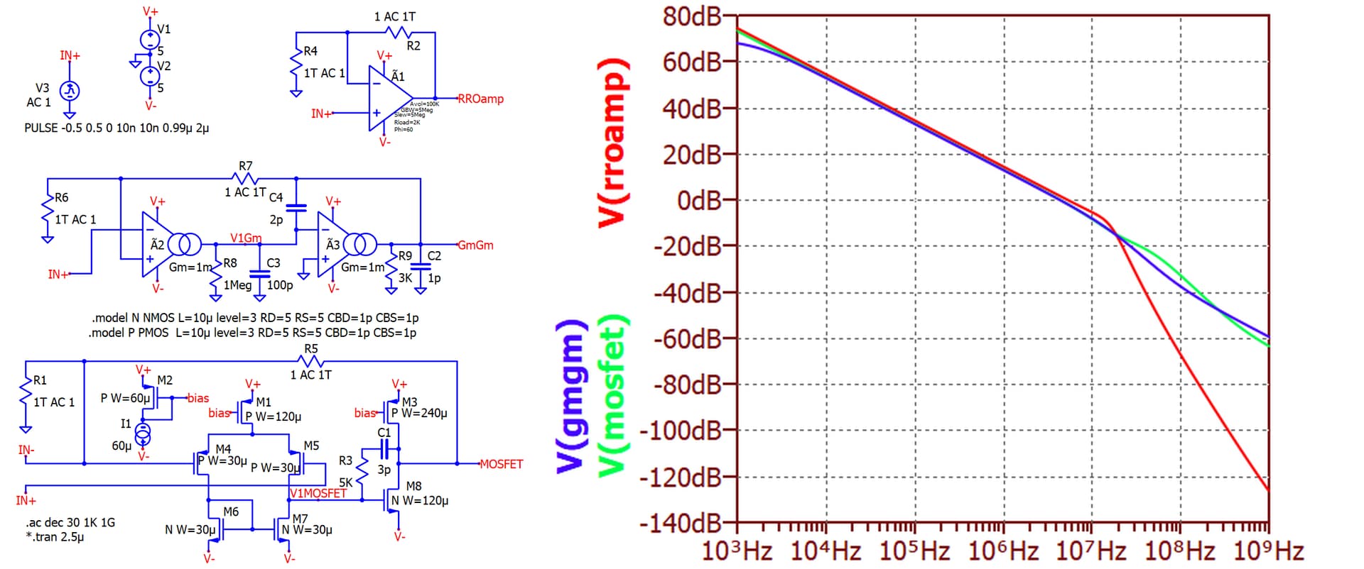
I am confused what topology the ‘RROPAMP’ Ã device is modelling. The documentation says it is to Gm blocks, with an optional ‘Miller’ compensating capacitor, but that would be two poles and a zero. The RROPAMP often (depending on parameters) has high-frequency gain falling at 60dB/decade, as if it had four poles and a zero maybe.
So I don’t really know how to use RROPAMP, but now MULTGMAMP does what I need (checking my math on small-signal noise in complicated situations, so I know what EN, ENK, IN, etc., I need before shopping for a real opamp.)
In my study, RROPAMP seems to behave in two mode, mainly determines by value of Phase Margin (Phi). If Phi=90, it behave as 2nd order function with two poles and one zero. If Phi less than 90, and depends on Cmiller, it can behave as 5th order function with five poles and two zeros. These extra poles and zero seems to set the phase margin as user specified.
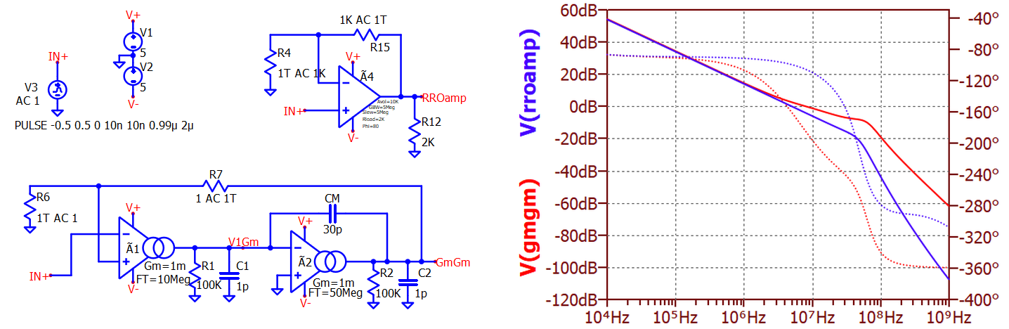
I still wonder what underlying model gives that transfer function, with 5 poles and 2 zeros, with the default parameters. The break in the transfer function amplitude just above GBW is so sharp that it must be a complex pair of poles. The help file says it is two Gm amps ‘as above’ [the MultGmAmp version] plus a compensating capacitor.
The MultGmAmp version of the à device has a parameter ‘FT’ that implements a bandwidth limit on the current output, which is then loaded by Rout and CapVdd + CapVss, so the output voltage would be the input times −Gm / (1 + s / 2π FT) × R / (1 + s R C) with two poles.
Two such amplifiers, with CM in the feedback position of the second, give very roughly
−G1 / (1 + s / 2π F1) × R1 / (1 + s R1 C1’) × { s CM − G2 / (1 + s / 2π F2)} × R2 / (1 + s R2 C2’)
(if I can estimate the effective capacitive loads as C1’ = C1 + G2 R2 CM and C2’ = C2 + CM)
So that’s just 4 poles and 2 zeros and I cannot replicate the behaviour of the default rail-to-rail op-amp.
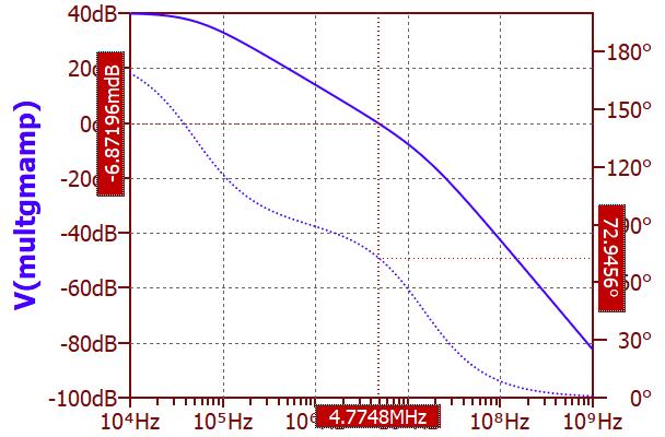
Not that I realise that the simpler MultGmAmp version can be a second order amplifier, that version will be enough for all my needs, and I haven’t even used the ‘Mult’ capability yet.
.subckt opamp IN+ IN- VDD VSS OUT
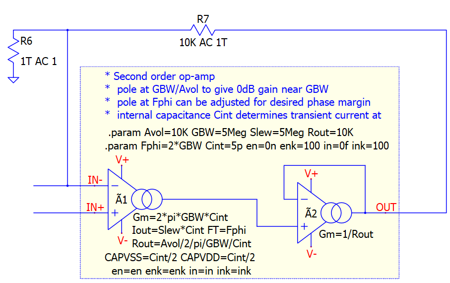
* Second order op-amp
* pole at GBW/Avol to give 0dB gain GBW
* pole at F2 can be ajusted for desired phase margin
.param Rout=10k Avol=10k
.param GBW=5Meg F2=15Meg Cout={1/F2/2/pi/Rout}
.param en=10n enk=100 in=5f ink=100
Ã1 VDD VSS OUT IN- IN+ ¥ ¥ ¥ ¥ ¥ ¥ ¥ ¥ ¥ ¥ ¥ MULTGMAMP
+ GM={Avol/Rout} Rout={Rout} FT=GBW/Avol
+ CAPVDD={Cout/2} CAPVSS={Cout/2}
+ en={en} enk={enk} in={in} ink={ink}
.ends opamp
I had another surprise [Edit: now resolved in the 28 August 2024 revision of Qspice]
The FT parameter of the MultGmAmp [formerly failed to limit] the bandwidth for intrinsic noise set with the EN parameter.
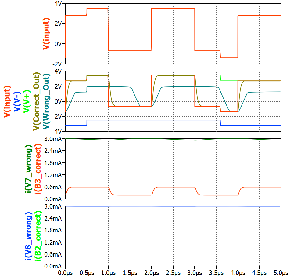
Unfortunately this OpAmp-Generic Rail-to-Rail Output OpAmp model model still fails basic functionality. The AC behavior was patch somehow to an usable level, but the power rails are still messed-up. The issue is random currents on the V+ and V- connections, both of them sourcing random levels of current. The negative power terminal V- is supposed to sink current (negative voltage), not source current like V+ (positive voltage). If this model would be used to analyze a real product, it could lead to catastrophic failures. Not production ready.
I agree that at this time we should not yet expect that R-R-Opamp is ready for general use.
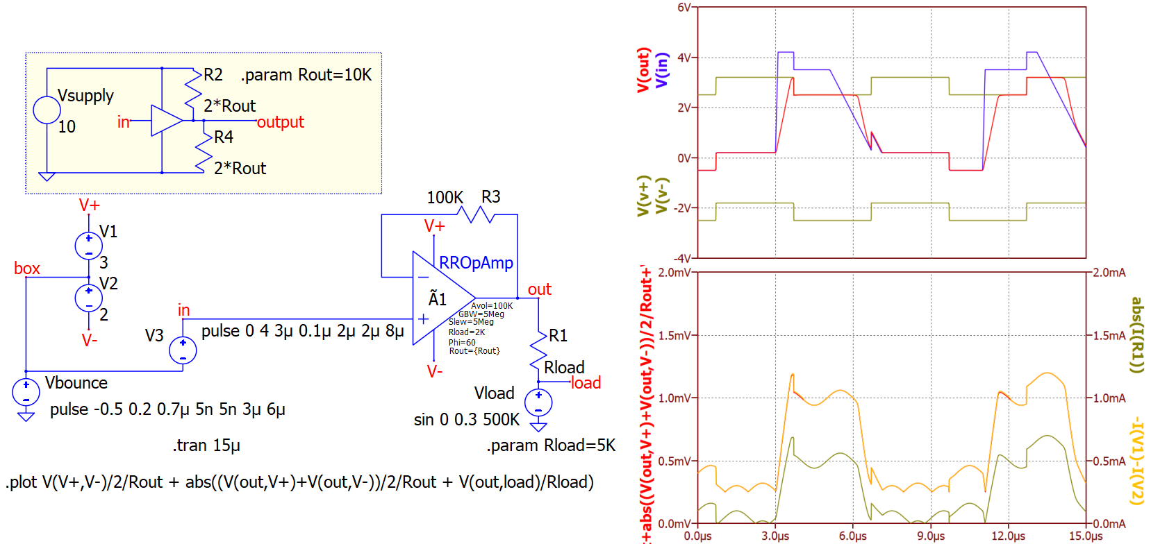
[Edit: The current draw in these examples, however, seems to agree with the description of Rout in the documentation.
Total supply current = (Vdd−Vss)/(2×Rout) + abs(V(out))(1/Rload+1/Rout) ]
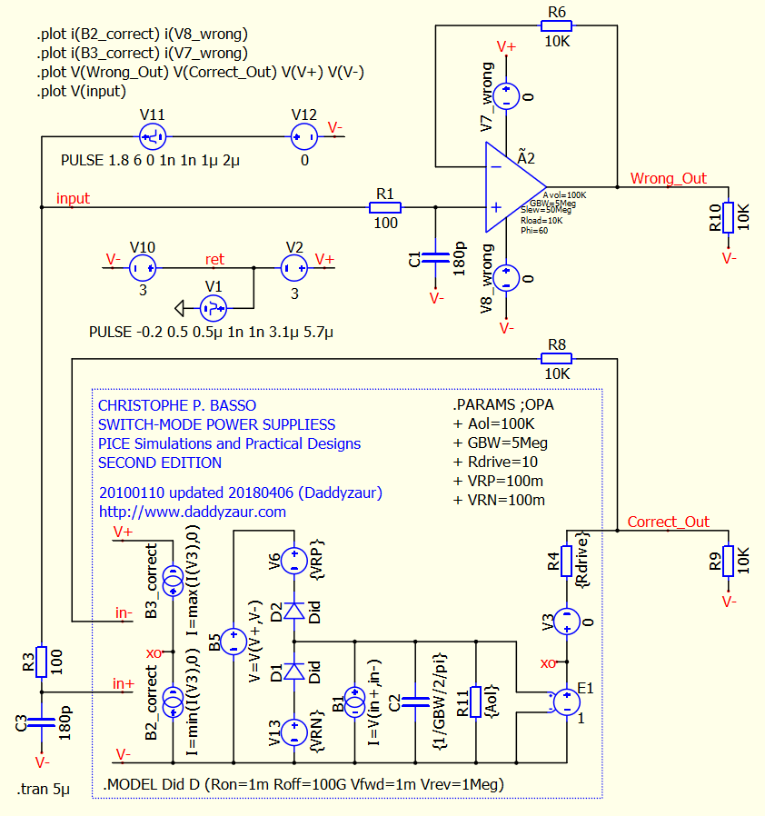
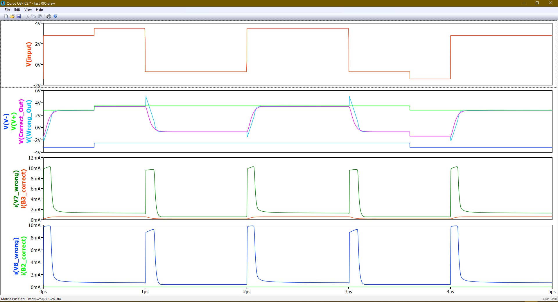
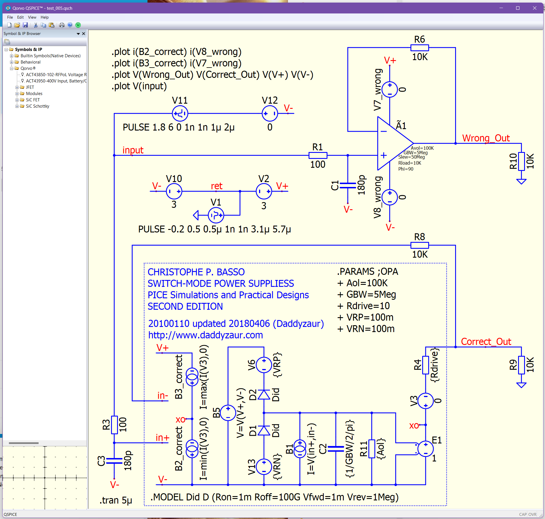
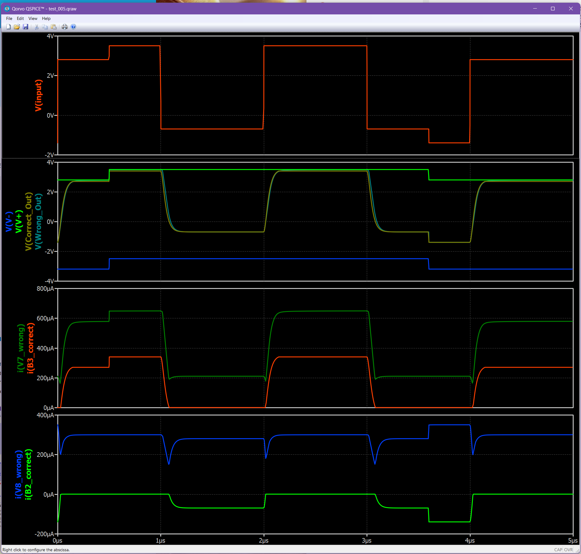
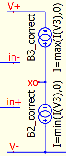
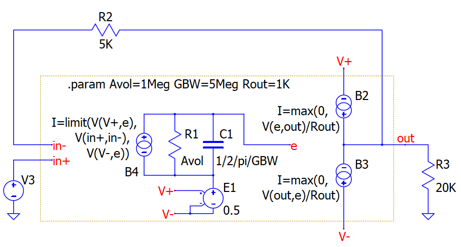
@daddyzaur Your negative-rail current has the wrong sign. Sources B2 and B3 are oriented in a way that they would realistically pass zero-or-positive current from V+ to xo, and from xo to V−. But the min(i,0) expression results in negative values for the current in B2, pulling current from V−.
Your model adapted from the Basso book is different in a few ways from what the R-R-Opamp is trying to do; Your model a first-order op-amp with output buffer, giving 90° phase margin, where only the drive current is sourced from the power rails, internal switching being done by internal source B5 that generates its own power to pull from the negative rail.
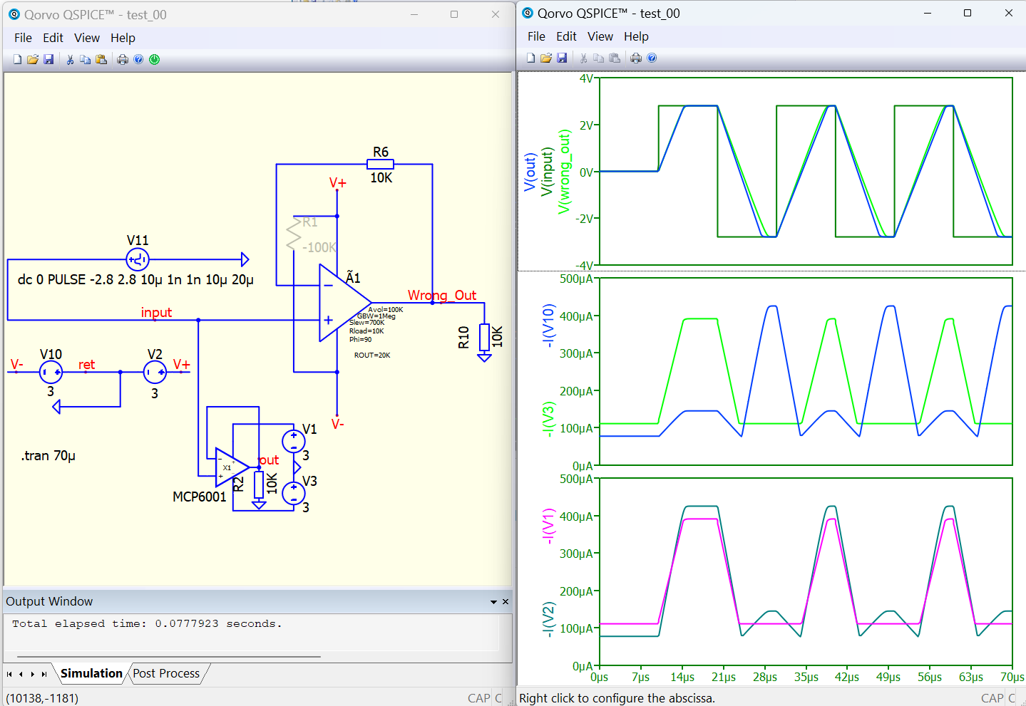
@bordodynov Your MCP6001 subcircuit in your Qspice schematic has a sign error in the calculation of the current draw from the negative rail. This error causes the sum of the currents into the device to be non-zero. (The PSPICE file from the manufacturer does not contain this error.)
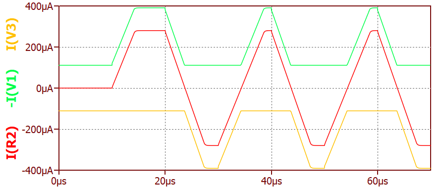
When V(out) is −2.8V the MCP6001 should be pulling 280µA through the 10k resistor, so should be returning 280µA to the negative rail and supply V3. However, the negative-rail supply current I(V3) was only 100µA, its smallest value, when the amplifier should be depending the most on the negative rail to pull V(out) below ground.
makes BD51(BD52) take sourced(sunk) output current from Vdd(Vss), makes the currents balance as they should, and comes closer to the currents drawn by the RROpAmp model.
Thank you so much for finding my mistake. I have corrected it according to your suggestion. The point is that I use this operational amplifier in my projects, and the factory model caused difficulties in LTspice counting. So I was forced to correct the model. I compared the corrected model and the factory model in SIMetrix. There were no difficulties for this program. I compared in TRAN analysis, but unfortunately I did not check the consumption currents.
Thanks OHara, I reversed the negative current source and added small resistors to identify the polarity.
Unfortunately you cannot use: Total supply current = (Vdd−Vss)/(2×Rout) + abs(V(out))(1/Rload+1/Rout)
Only in an extremely narrow window of DC applications something like that could work with an OpAmp, and only when all inputs, outputs, and power rails are referenced to ZERO (GND). As soon as the loads, the inputs, or the power rails are floating/bouncing, the relation becomes meaningless. How can one use DC calculus for a circuit with complex and/or active loads?!?
The trick with reading the current into the output and mirroring that value back into/from V+ and V- is the only way I found to get some realistic power rail currents. Yes, one can add many other internal functions, read their current, and reflect them back into the V+ and V-, for whatever internal functions are needed. For most applications the bulk of the V+ and V- current is the current sent into the output load, that is the common denominator for all OpAmp applications. test_007.qsch (26.3 KB)
My point with the expression for total-supply-current was that the RROpAmp draws a lot of quiescent current depending on its parameter Rout.
By my interpretation of the documentation, the RROpmAmp uses an infinite-impedance current-source as output and adds 2*Rout to each supply rail to get the requested Rout (which seems a strange approach to me).
The expression for total supply current is a bit messier if the load is referenced to a ground different from (Vss+Vdd)/2, but not too messy, and it explains the current draw of the RROpmAmp being larger than what flows through its load.
True, that simple quasi-DC estimate misses the spikes of current when internal capacitors charge and discharge. Those spikes used to be large, in QSpice before August 2024, but now the simple estimate covers the detailed simulated current-draw in the plot.
I still think the RROpAmp device is not a good choice for generic op-amp in early stages of circuit design; it was meant as a tool for building computationally-efficient representations of real op-amps.
The idealised op-amp on KSKelvin’s github is better as a generic op-amp. We can remove ground references and make it respect the power rails if we use nonlinear B-devices:
To get noise density for the Spice .noise analysis, though, we need one of the proprietary Qspice Ã-devices. I like the simpler MultGmAmp, and use a second stage with feedback so I can get reasonably low output impedance in I think a more realistic way.