Fault in a parameter not found in the subcircuit

After learning in on making libs and handling nested subcircuits, I have one that finally works.
I have come up with messages of say: param1.param2.X1 where working backward I can find those things in the spice subcircuit but this one is not there. Below is the total messages (I.X1 near the end):

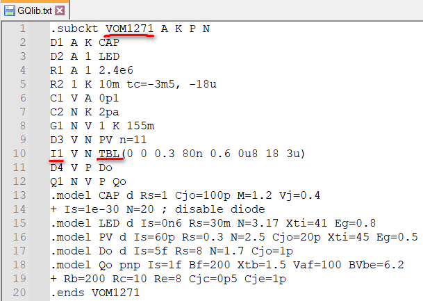
Warning: Ignoring unknown instance parameter “TBL•X1” of device I1•X1.
Warning: Unexpected number, “0”, in device I1•X1.
Warning: Unexpected number, “0.3”, in device I1•X1.
Warning: Unexpected number, “80N”, in device I1•X1.
Warning: Unexpected number, “0.6”, in device I1•X1.
Warning: Unexpected number, “0U8”, in device I1•X1.
Warning: Unexpected number, “18”, in device I1•X1.
Warning: Unexpected number, “3U”, in device I1•X1.
C:\Users\A53461\OneDrive - Microchip Technology Inc\Gstuff\SIM\ITR-4.qsch
Warning: Source I1•X1 has no value, 0 assumed
BSIM3v3.3.0 Parameter Checking. Model = SMSMOSFET•X2

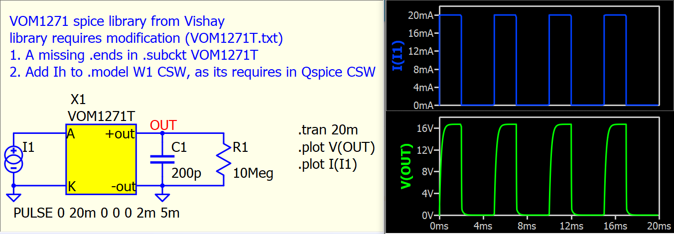
So, X1 is the component in the schematic and the circuit is:

.SUBCKT VOM1271T A K -out +out
XU1 A K 0 N001 VO1263
XU2 +out N001 +out 0 I-FAST_TOFF
.ends

.SUBCKT I-FAST_TOFF Iin Iout NC2 NC1
V1 Iin Iout 0
W1 NC1 NC2 V1 W1
.model W1 CSW(Ron=100K Roff=10Meg IT=1uA)
.ends

.SUBCKT VO1263 A K -Iout +Iout
XU1 A K N001 K IRLED1
XU2 N001 K -Iout +Iout GAIN-MOD
R1 -Iout +Iout 1Meg

  • Zout of driver
    .ends

.SUBCKT IRLED1 1 2 3 4
F1 4 3 V1 1
V1 5 2 0
D1 1 5 D1
.model D1 D(IS=1P N=1.948621 RS=1.560495 BV=6 IBV=10U CJO=18.8P VJ=0.532794 M=0.27985 EG=1.424 TT=500N)
.ends

.SUBCKT GAIN-MOD +Iin -Iin -Iout +Iout
F1 -Iout +Iout V1 0.001
*current gain of driver
V1 +Iin -Iin 0
.backanno
.ends

I expected to find I1 in there (that’s eye one) but no.
Any ideas what it refers to?

Thanks

Gary

I believe you may not have the file upload capability in this forum yet.
Please consider using this method to upload your netlist into the forum (you may also need this to paste your subckt if your subckt is called with .lib). Without a way to quickly replicate your simulation, it becomes very time-consuming to provide assistance.

* C:\Users\A53461\OneDrive - Microchip Technology Inc\Gstuff\SIM\ITR-4.qsch

.libpath "C:\Users\A53461\Documents\SIM\GpartsQspice"
.libpath "C:\Users\A53461\OneDrive - Microchip Technology Inc\Documents\QSPICE\Glib"

R1 N01 TK2 1K
V2 N01 0 24V
R3 TK2 0 1K
V8 N02 0 pulse 0 10 0 5n 5n 200µ 400µ
M3 N04 N02 0 0 2N7002 NMOS
R14 N02 0 10K
V1 N03 0 12V
R9 N03 N06 120
X2 TK2 N05 0 NMOS_TK290P65Y
X1 N06 N04 N05 0 VOM1271
.tran 500µ
.param R1=260K
.param Rvar=160K
.lib "C:\Program Files\QSPICE\NMOS.txt"
.lib "C:\Users\A53461\OneDrive - Microchip Technology Inc\Documents\QSPICE\Glib\GQlib.lib"
.end

GQlib.txt (167.2 KB)

I have it as used in a library - renamed .txt as .lib was not allowed.
Is this usable?
Many thanks

Oh, you can upload file? Please attach .qsch.

About VOM1271
I download VOM1271 spice model from Vishay, and the reason that this library cannot run properly in Qspice is that

  • It missing a .ends in .SUBCKT VOM1271T
  • Qspice syntax requires CSW with IT and IH, and have to change .model W1 CSW(Ron=100K Roff=10Meg IT=1uA) to .model W1 CSW(Ron=100K Roff=10Meg IT=1uA IH=0)

Here is a package that with modified library and an example of .qsch.
Qspice support library with .txt and I normally rename library to .txt as it allow upload to forum if required.

VOM1271T-Qspice.txt (4.3 KB)
Parent.vom1271.qsch (3.3 KB)

Wow, I’d be a ways off finding that.
I did find the .ends missing - Qspice told me that :slight_smile:
Many thanks for the fixes.

I still don’t understand the messages though referring to TBL.X1 and I1.X1 that I don’t see
Can you explain those please, or better still point me to a doc that explains where syntax is different to industry produced models?

Gary

That warning is related to .subckt VOM1271. In your netlist, X1 calls to use VOM1271, and its I1 uses TBL function. TBL is an alternative form of function TABLE ( B sources (complete reference) - LTwiki-Wiki for LTspice). This alternative form also support in Qspice, but I have no idea what is the meaning of I1 V N TBL(0 0 0.3 80n 0.6 0u8 18 3u), as table requires an input with odd number of arguments, but this table is even number. But most importantly, in Qspice, table data needs to be separated with comma “,” and not space. You can force this .subckt to run without error by changing that line to

I1 V N TBL(0,0,0.3,80n,0.6,0u8,18,3u)

But again, I have no idea what is its meaning.

That why I searched for VOM1271 in internet as I have to get its datasheet to understand what I dealing with. I found it from Vishay (which is .subckt VOM1271T), and therefore, I just worked on that one.

image

Impressive, and thanks for info. I’m off sick at present but that looks like a different spice file i found on a forum when the multi-subcircuit one didn’t work. Now I’m confused about what i was running as I’m sure i came to you only with the multi- subcircuit one. I’ll investigate what i did…

1 Like

OK, I found that single subcct still in my main library file and it picked it up first and it wasn’t the multi-subcct one I thought I was running.
I made your change adding commas, but it doesn’t work well - well, not at all really.

They work well with the current drive input and 10Meg output as you tested.

But with a switched voltage input (pulse voltage into a FET gate turning on/off 5V drive into VOM1271 LED input) and VOM1271 output driving FETs (one at a time) I’ve added to my library. FETs make a huge difference to VOM1271 output drive into gate.

They should work as I have Ccts built up with real devices to test.

Gary