Hi All,
I have been working on creating examples on how to generate Digital PWM as fast as possible for Digital SMPS simulation.
Brief explanation presentation can be found here:
Three Complexity Levels of PWM Implementation for Digital Controller Simulation.pdf (866.2 KB)
Simulation file can be accessed in https://github.com/physicboy/QSPICE/tree/main/PWM_example_SRbuck
The technique explained briefly in this article explained the method to speed up the simulation by exploiting the Trunc() feature in C-block function in Qspice.
The same method has been used for Totem pole PFC simulation, that gives me 2 sec transient simulation in only 21 sec
6 Likes
Great presentation, and a nice fast simulation. Do you have any comparison points for how much faster this approach is versus other simulators?
Dear Arief,
I found your buck-converter examples quite interesting and really useful: thanks for providing such a good starting point to learn how to use C-blocks.
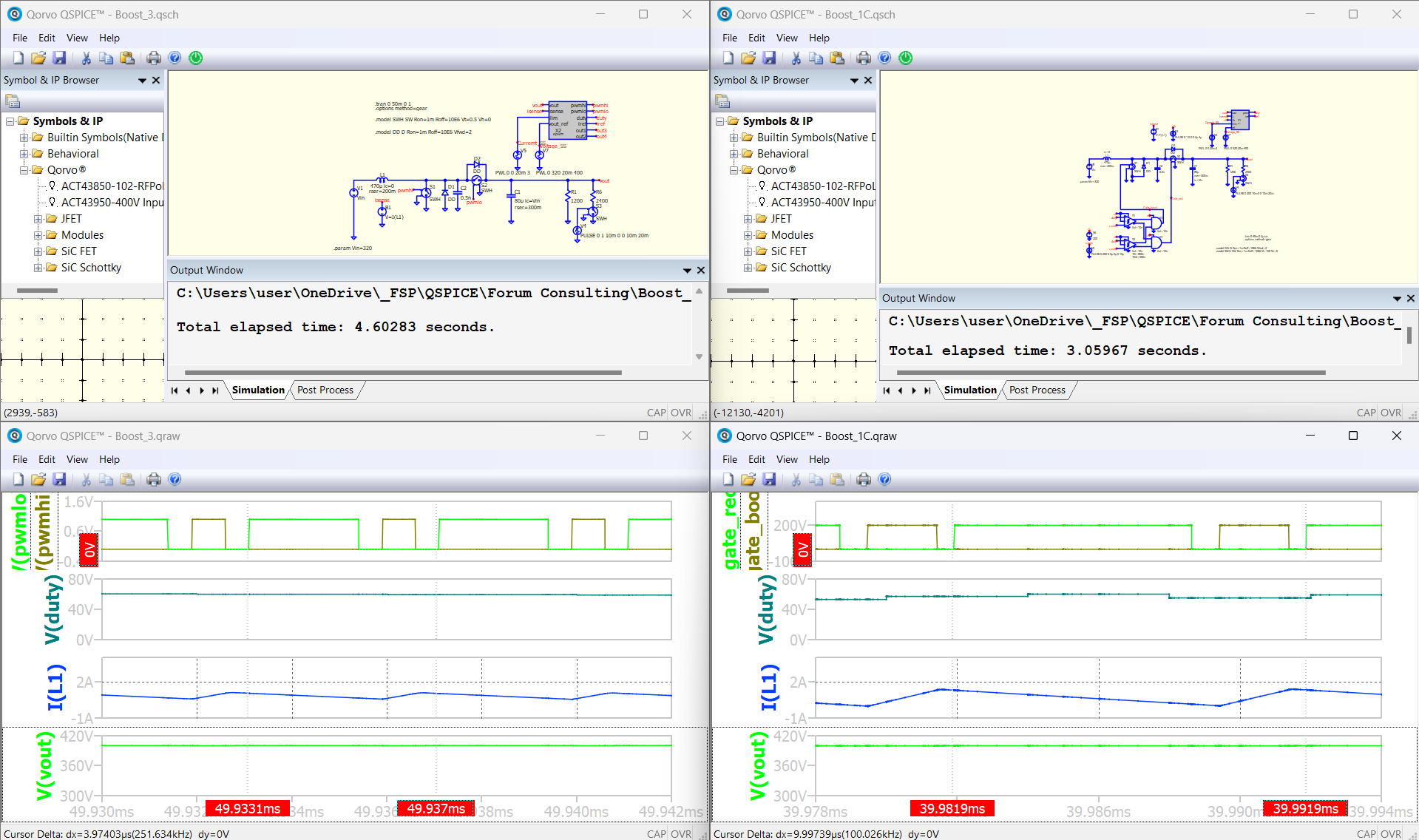
Starting from your code, I tried to develop similar boost converters. In particular I converted the Level 1C and the Level 3.
What is not clear to me, is why they behaves differently: the 1C is stable, while the 3 is not.
They should be identical from the electrical point of view, and also with the same carrier frequency and PI constants, but they behaves differently: is it my fault? What am I missing?
Thanks for supporting this learning phase!
Francesco
Boost_1C.qsch (25.0 KB)
lev1c.cpp (4.3 KB)
Boost_3.qsch (15.9 KB)
epwm.cpp (8.2 KB)
1 Like
In short… There are a few mistake due to my limited understanding back when I made those example…
For the past a few weeks, I and @RDunn and @KSKelvin has been discussing intensively and comeout with a collective understanding on how the Trunc() works and what should we do to effectively working with it.
So:
- I will review your code, and I will let you know more about it
- I will update my example soon
Arief
1 Like
HI @FrancescoA
For whatever reason, your two simulation run at different switching freq.
Boost 1C at 250kHz and Boost 3 at 100kHz
It should be quite straightforward for you to fix
1 Like
I missed this back when it was posted originally. This is a great study of how to use the C block to get faster simulations.
I have a question about timing for the level 1, 2 and 3 simulations. For level 1 there is a clock that defines the switching frequency (i think) but in level 2 and 3 what defines the switching frequency?
Thanks
-J
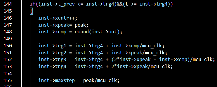
@jay314159265 The timing control is performed by this line
The line 150 and 152 dictate the PWM output transition point
The line 151 and 153 dictate the Carrier period and Half period mark.
To everyone reading this post, the timing control for these example in my Github page has been modified to follow my latest understanding of Trunc() behavior as per 2024/3/22.
The difference is with the timestep control:
where previously, the future timing is computed against future simulation time “t” within Trunc.
in the new version, the future timing is computed against the previous simulation time “inst->t_prev” within the Trunc.
The reason is due to my misunderstanding about the behavior of “t” and “*timestep”
However, please note that the explanation article (.pdf and .ppt) are not yet updated, I am having a hard time forming the right explanation of my method.
1 Like
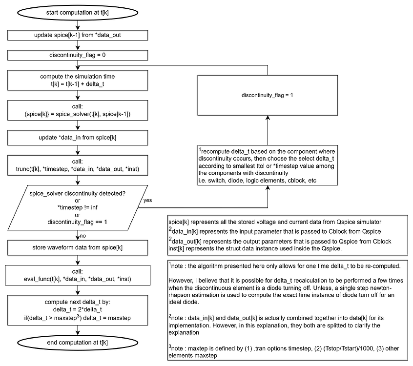
Anyway,
This is the flowchart that explained my current understanding of the interaction between Qspice main solver and the .dll functions as performed by Trunc() function as it handles the future timestep modification.
According to this understanding, I then came out with this idea as I shown in my Example to directly manipulate the future timestep that I believe matched very well with the behavior of digital controller.
1 Like
Hi @physicboy , yes, you are right, the uploaded examples use a different PWM frequency.
Unfortunately I commented the wrong line just before uploading the Boost_3 code.
Please find attached the correct version with the same 100 kHz PWM as the Level_1C.
epwm.cpp (8.2 KB)
Nevertheless, the behaviour is anyhow different, being my Level_1C boost converter stable, while the Level 3 not. Boost_3.qsch (15.9 KB)
Why the two simulations behave differently? They should be the same from the physical point of view.
BTW, you wrote that you changed the examples after your better understanding of the Trunc() staff, but I’m sorry I cannot see what (which lines) yuo modified.
Sorry for this late reply, but I was on holiday 
The modifications are on the following lines.
if(inst->t_prev < inst->trg1){*timestep = (inst->trg1 - inst->t_prev);}
if(inst->t_prev < inst->trg2){if(*timestep > (inst->trg2 - inst->t_prev)){*timestep = (inst->trg2 - inst->t_prev);}}
.
.
.
In previous version, the comparator and *timestep calculation are done against “t”, and new one against “inst->t_prev”.
About your boost sim, I will check it tomorrow
Hi @physicboy , I’ve now understood that the sampling frequency of the Level 3 is the same as the PWM carrier, while in the Level 1 it is set by the external “clk”. Actually, forcing the “clk” of Level 1 to 100 kHz, which is the same carrier frequency of my Level 3, a similar instability appears.
Honestly I can not understand why I must sample so frequently the input to gain stability…
Thanks for clarifying what you changed in your buck examples!
And thanks for keeping helping us!
Glad I can help
That’s great that you found your issue. I may not be able to locate that problem immediately as I am not going to do that.
There are a few things that you need to be aware of when designing a digital control:
- For fixed pwm freq, the sampling is done synchronously with the pwm carrier. It can be done as Fsampling = Fpwm, or Fsampling = Fpwm/N, where N = 1,2,3,4,…
- For variable freq system (i.e. LLC), the sampling can be done synchronously or at asynchronously lower sampling frequency.
- Lower sampling frequency can degrade the control performance by introducing more delay to the system loop. Thus lowering the phase margin.
- If you are not careful, you may significantly alter the integrator gain when changing the sampling frequency.
Arief,