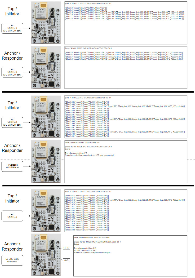
I am trying to get the DWM3001CDK working in standalone operation as an anchor/responder without having it connected to a USB host. My setup uses the latest “DWM3001CDK DK Software, Sources, Tools and Developer Guide.zip” and has two DWM30001CDK devices where one is configured as a responder and one is configured as an initiator. The setup of the responder is stored on the NVM and the RESPF application starts automatically as soon as the device is connected to a power supply. Everything works nicely as long as both devices are connected to a USB UART. However, there are errors in the ranging if the responder in not connected to a USB UART.
Does the firmware provide the option to run correctly in standalone mode or does it currently require a USB UART connection? I built the “DWM3001CDK-DW3_QM33_SDK_CLI-FreeRTOS.emProject” and stepped through it with the debugger but I don’t yet understand how everything works together.
Could it be that the UART output causes the issue when no USB UART is connected? And if so, what do I have to look in the code for to disable it.
How to switch to the UART connection on the Raspberry Pi header and disconnect the USB UART without issues? I managed to activate the UART connection on the Raspberry Pi header (command “uart 1” on CLI, followed by “save”) but the device still requires an active USB UART connection to work correctly.
Hi @christian.i
Im not familiar with the demo code.
But:
On DWM3001CDK is a STM32 chip which behaves as SWD debugger and USB to UART bridge. From this point of view it should not matter is the RPi UART is used or if you use the USB.
I dont think it is an UART issue at all
I pretty much convinced that is is your powerbank who generate the issue. Some power banks contain poor DCDC converters which are working very badly (very high noise) with low power load. Try to replace the power bank with some adapter first to double check that.
Most of the newer powerbanks has a “smart power” feature which cut off the power output when it detect a low current at its output - it also can cause target power cycling - double check that. For example to bypass this I have created a cable with addition resistor load.
thanks for your input, but I don’t think it’s only due to the powerbank. I also used a laboratory power supply to hook the board up via the RPi header. In that case there are also problems with the communication as shown in the images above. For me this indicates that the SW behaves differently depending on whether the UART is connected via USB or not. Also, switching to the UART on the RPi header does NOT turn off the USB UART - it remains active an can be used to controll the board at the same time.
Still, my main question is whether the SW currently works as intended without an active USB UART connection. I assume that saving the responder application (so that it starts at power-up) should do the trick, but I can’t get it working.
Maybe someone can confirm whether the responder app works without active USB UART connection.
Hi @carlos.silva , please take a look at my post when you have the time. The responder app seems to require a USB UART connection to work properly. Do you have an idea in mind of how I can make it work?
Hi @christian.i ! Weird that I didn’t see the notification for this message!
How did you set the DWM3001CDK role, CLI “initf” plus “save”?
It seems to be an issue with the report function. If the USB is not connected the embedded app gets stuck, even able to range.
You can try to remove the report part “reporter_instance.print” or disable the USB.
If you need to start FiRa ranging in code (because CLI is not available), add “scan_fira_params()” to main:
scan_fira_params("initf 2 2400 200 25 2 42", true); // Change to false if responder
And inside “\Src\Apps\Src\common\app\common\app.c” set the “DEFAULT_APP” to “helpers_app_fira”:
Hi @carlos.silva, thanks for the instructions. I changed the FW to automatically start the responder app with my parameters, and disabled the UART communication by removing the define USB_ENABLE from the project preprocessor settings. However, that didn’t fix the FiRa ranging problem.
It seems that the issues is related to the USB driver but independent from the UART communication.
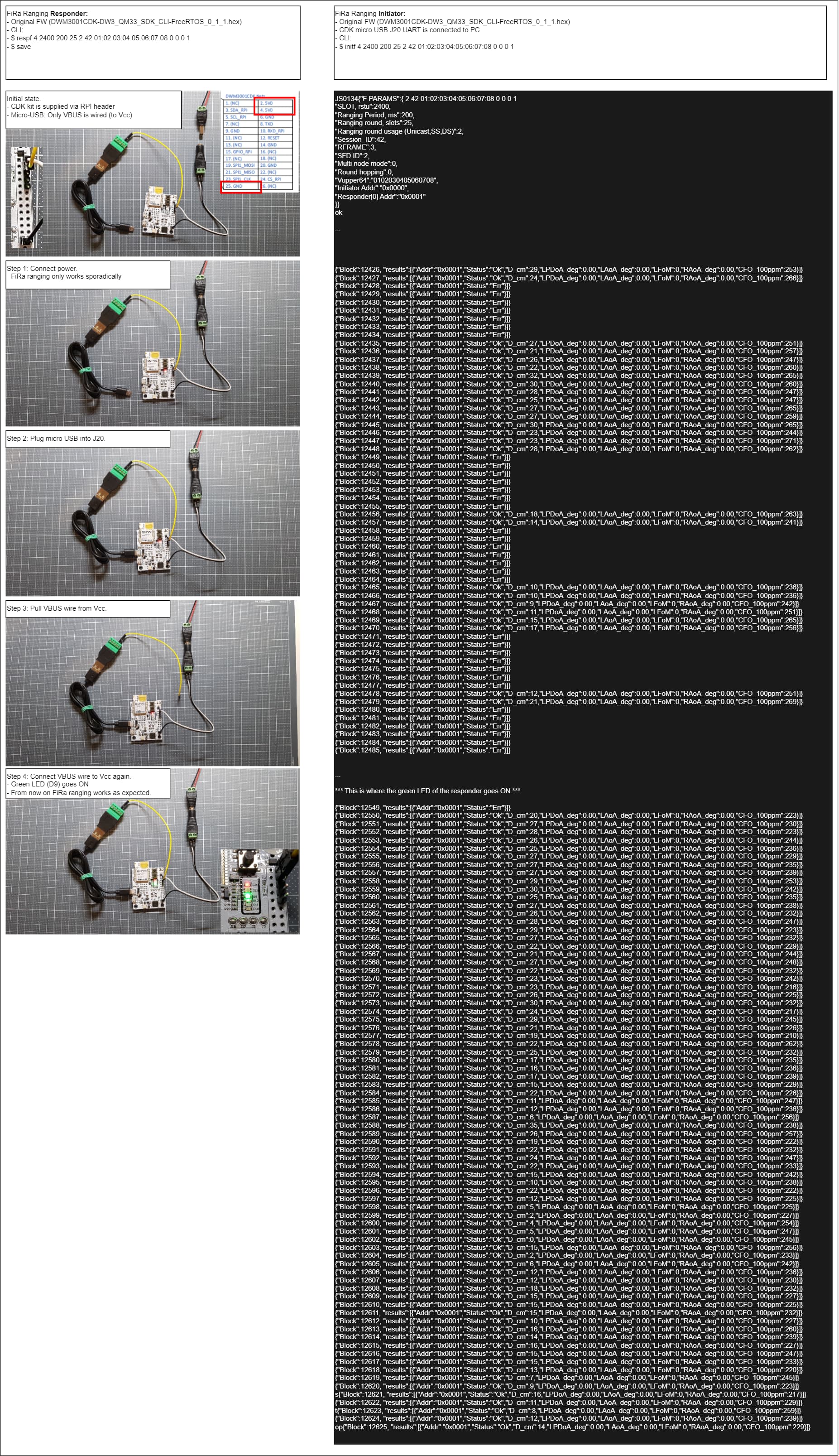
I flashed the original CLI FW to prevent any side effects of my changes. I can also rule out any power supply issues because I get the same results with a laboratory power supply and batteries.
This is what I found out:
The FiRa ranging works as expected as soon as the green LED D9 on the responder board goes ON.
This happens in the function “usbd_user_ev_handler(…)” in “\Src\HAL\Src\nrfx\HAL_usb.c”
static void usbd_user_ev_handler(app_usbd_event_type_t event)
{
    switch (event)
    {
    case APP_USBD_EVT_DRV_SUSPEND:
        bsp_board_led_off(LED_USB_RESUME);
        break;
    case APP_USBD_EVT_DRV_RESUME:
        bsp_board_led_on(LED_USB_RESUME);
        break;
    case APP_USBD_EVT_STARTED:
        break;
    case APP_USBD_EVT_STOPPED:
        app_usbd_disable();
        bsp_board_leds_off();
        break;
    case APP_USBD_EVT_POWER_DETECTED:

        if (!nrf_drv_usbd_is_enabled())
        {
            app_usbd_enable();
        }
        break;
    case APP_USBD_EVT_POWER_REMOVED:
        app_usbd_stop();
        break;
    case APP_USBD_EVT_POWER_READY:
        app_usbd_start();
        UsbSetState(USB_CONFIGURED);

        break;
    default:
        break;
    }
}
“case APP_USBD_EVT_DRV_RESUME:”
bsp_board_led_on(LED_USB_RESUME);
To me it seems that the USB driver has to reach a certain state before the responder app can work properly.
The state can be reached in a reproducible manner as described in the picture below.
In order to get the green LED D9 ON, there MUST be a micro USB connector plugged into J20. Only providing VBUS via the test point pad TP14 does NOT work. So it seems to me that the plug detection is involved.
At this point I’m stuck. I want to start the responder board by just connecting the power supply. I have no idea about how to solve the USBD issue.
this does not happen with the V3 sdk CDK binary loaded. I am testing powered on the j9 connector, usb power leads only and the board is providing ranging (client)
Hi @rexxdad, the current download from the qorvo product page (link) is DWM3001CDK SDK 0.1.1 (which includes DWM3001CDK-DW3_QM33_SDK_CLI-FreeRTOS_0_1_1.hex). What V3 SDK binary are you referring to?
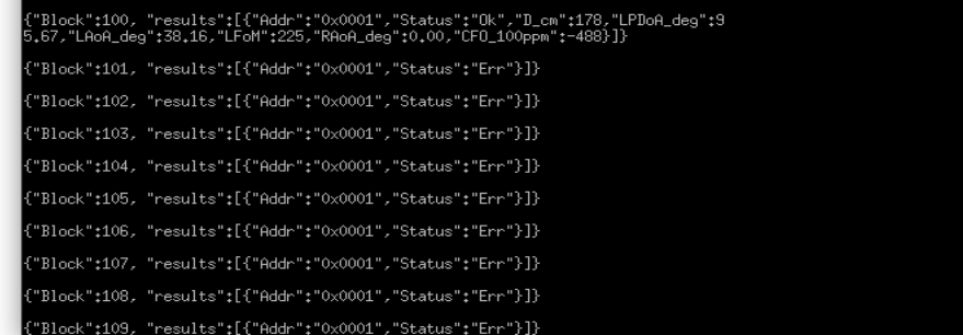
I tried to reproduce your setup with DWM3001CDK-DW3_QM33_SDK_CLI-FreeRTOS_0_1_1.hex, but I only get a singe range measurement, the remaining output is all errors.
Hello @carlos.silva, did you by any chance find where the app is waiting for a USB connection? I am trying to run the device without connecting it to a computer, but it seems that I only obtain one successful response when the device first starts, and everything after just fails.
Still working on it.
Not sure how the issue is related to USB, but the chip is taking too long sleeping and a workaround would be to change DEEPSLEEP_WAKE_CONSTANT_DW3000_us to a very high value in \DWM3001CDK-DW3_QM33_SDK-FreeRTOS\Src\UWB\dw3000_lp_mcu.h
Using like this, I got it working:
I was working on a solution around a week ago, and I found something that might be of use. I currently lost access to that solution, but I still have an idea on what I did. In SDK_BSP/Nordic/NORDIC_SDK_17_1_0/components/libraries/usbd/app_usbd.c where the app_usbd_event_execute function is, I moved the portion of the code related to the resume outside the switch statement, and run just that. The idea is to force the device to resume without having to wait for a usb connection event. To some extent, it worked. I managed to plug my device to an external power source, but it had some negative outcomes. For example, the boards should be facing each other at a very delicate angle in order to obtain successful transmissions, and a slight change in the angle would affect that. Moreover, I placed the devices at a farther distance ~6 meters, and I wasn’t able to obtain any successful transmissions.
I apologize, but I cannot fully remember what I changed in the code back then.
This is not the best approach, but hopefully it could assist you. As for your solution, I will give it a try as soon as I gain access of the devices again.
I just figured out what was happening, I was looking for low-power functions inside both USB and UWB code, but it was actually the HFCLK.
The HFCLK is used by the USB driver, the nrf_drv_clock_hfclk needs a request for each peripheral/resource using it, USB has a request, but UWB doesn’t. The nrf_drv_clock_hfclk is set like only USB is using it and when USB releases it stops. The solution is to add a new request for UWB:
In main_cli() look for BoardInit(), it calls peripherals_init() which has the clock initialization.
There you will find a call for nrf_drv_clock_lfclk_request(NULL), right before this line you should add the nrf_drv_clock_hfclk_request(NULL).
This single call will solve the problem, but Nordic sets the call with a verification before proceeding:
   nrf_drv_clock_hfclk_request(NULL);
   while (!nrf_drv_clock_hfclk_is_running())
   {
       // spin lock
   }
Well, that’s it! Thanks for spotting this issue!
Kind regards!
Hey @carlos.silva thank you for this solution! I will try it out when I gain access to the devices and let you know if I face any issues. Glad to be of help!
I tested the fix and it works! Took me a while to figure out how to compile firmware. I am running 8x anchors and they save their commands and automatically start, either with USB power or battery. I have a single tag at the moment.
For future-me reference:
The IDE is Segger Embedded Studio for ARM. To load the firmware source, go to C:\UWB\DWM3001CDK_SDK\Sources\DWM3001CDK-DW3_QM33_SDK-FreeRTOS_0_1_1\DWM3001CDK-DW3_QM33_SDK-FreeRTOS\Projects\DW3_QM33_SDK\FreeRTOS\DWM3001CDK\ses and double-click on the DWM3001CDK-DW3_QM33_SDK_CLI-FreeRTOS.emProject file. It will automatically load the entire project into Segger. You then search for nrf_drv_clock_hfclk_request(NULL) across entire project to find the right file to edit.
Yup it works! Thank you @carlos.silva !
Also @Costas for the last sentence, I think you made a typo. You should search or nrf_drv_clock_lfclk_request not nrf_drv_clock_hfclk_request