A spreadsheet for estimating the lifetime of a battery powering a DWM1001 tag in a PANS-based RTLS has been created. You can use it to get an indication of how long a typical battery will last in the system.
Accompanying application note, APH011, gives instructions and a comparison with measured results.
Calculations and measurements are made using PANS Release 1. It is expected that a slight improvement in battery lifetime should be seen with Release 2.
The RT8059 has quiescent current of 78uA. I don’t see an account of that in this calculation. Am I missing something?
I notice that in the schematic of the DWM1000, there is a signal called “DW_EXTON” that I think could be used to enable/disable the DC/DC converter in a way that could eliminate the 78u when the regulation isn’t needed…but I don’t think it is accessible at a module pin.
Hi,
The quiescent current is ultimately reflected in the regulator’s efficiency and this is how it’s accounted for.
You’re quite right about the importance of disabling the 1V8 DCDC when it’s not required. This is why the shutdown current spec for that DCDC is so important. The 1V8 DCDC is only enabled when needed in PANS firmware.
The 1V8 DCDC is usually controlled from the DW1000’s EXTON logic output, so you wouldn’t need to have a separate signal on a module pin.
Ah I think I understand what you are saying - the efficiency should be modified based on use case.
For light load conditions (ranging rates <1Hz), the 78u becomes quite significant. I would need to adjust what I enter for power efficiency accordingly to get a better estimate of battery life in that case.
This is the quiescent current, not a shutdown current - this DCDC is enabled by DW1000 if the latter in some active state. And it consumes milliamps in such a state - so 78uA is negligible.
In sleep/deepsleep state the DCDC is switched off so you need to pay attention to 0.1uA typ.shutdown current of RT8059, as SC stated above.
The 1.8V regulator is internal to the DWM1001 module - I understand that it is controlled by the EXTON signal to save power and that its shutdown current is what is consumed during that time - not its quiescent.
However, I was referring to the external RT8059 which provides the 3.3V to the module (and the input to the internal 1.8V DCDC). I think it must always be enabled unless you want to completely shut down the module. That’s why I believe there is always 78u drawn from it…which is significant for lower ranging rates when the avg. current draw is sub mA.
Oh, I see. You are talking about the whole MDEK kit.
Completely agree.
The dev board I think was not designed for low power.
Also should point out that you also need to disable ST MCU containing J-Link FW (it consumes several milliamps), can easily be done by desoldering some bridges.
Related to this issue - RT8059 quiescent current is important and 78ua is too much .
I searched for a while and XC6206 series , seem a reasonable option. However, I purchased some of these regulators from china and after assemblying them on board, We found out that their consumption is 400ua in standby which is unbearable for our case . Probably my regulators were not original. but if you could find original one, it has 1ua Iq which is great for this use.
Hello Alec, we have tried opening the J16 bridge,who accordong to the manual is the power of the J-Link, but the tag doesn’t power-on, do you know who are jumpers that we must open to disable the J-Link consumption?
Thank you
I think you should remove J6 - it’s a Reset from J-Link, after it is powered off it seems holding the DWM1001 module in reset state.
Also suggest to remove J17 and J18.
Hi inaki,
Remove J14 and J15 aswell to enure any leakage is eliminated.
This is outlined on page 10 of application note APH011, which accompanies the estimator tool.
Hey Guys,
we need to get an average lifetime of 1 year at least.
We desolderd every bridge described in the document, only LE and SD was enabled. The frequenz was set to 0,2 Hz stationary as well as normal upd rate.
The estimated Lifetime was 791,32 days with an average current of 0,03 mA
but we measured an average of 150 mA.
Our first test was with an Gold-Cap capacitor to simulate a Batterie with a linear loss in current.
Through our calculation we estimated a lifetime of 2 hours for the capacitor but only got 5 minutes.
We thought how that could be possible and made a measurment with a current tongs.
I can’t guarantee that the times are 100% accurate, but it would be highly unlikely.
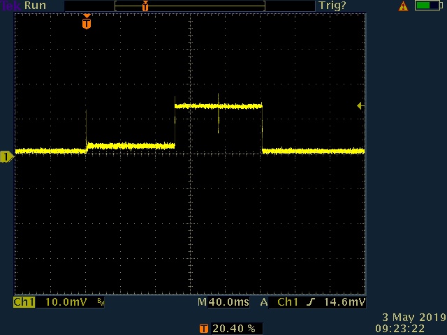
The peaks of the current are correct, first we got the wake up phase with a peak of around 13 mA but instead of 1.5 ms we got around 100 ms, than we got the sending signal with a peak of around 130 mA but instead of 4 ms we got again 100 ms. Cause of this our capacitor only had a lifetime of 5 minutes instead of 2 hours. Can someone help us to sovle this mess.
PS: The measurements were made in the laboratory and there were no anchors near
I think that the current is much more different because you don’t have anchors, the tag is probably in RX mode more than usual because it’s trying to listen for anchors. Plus, the tag will not perform the Two-Way Ranging so you won’t have the correct current measurement anyway.
Try with at least 3 anchors nearby so that the tag is in normal operations.