Below is a cutdown/simplified version of a PFC boost stage. In some cycles the diode fails to turn off (resulting several µs and several amps of reverse current with simulation points).
Notes:
- Happens with real and ideal diode pairs
- Simulation time is long (to cover a 50Hz cycle) but have found the issue can be mostly fixed by setting the max step time to 50ns (much smaller max step with ideal diodes; setting max step increases the processing time and becomes an issue once the full circuit is added back in)
- In the full version I fixed a timing issue on a Schmitt trigger by using TTOL (works nicely as it only increased the number of points when required) but can’t seem to find a similar feature on a diode.
Any help or explanation appreciated.
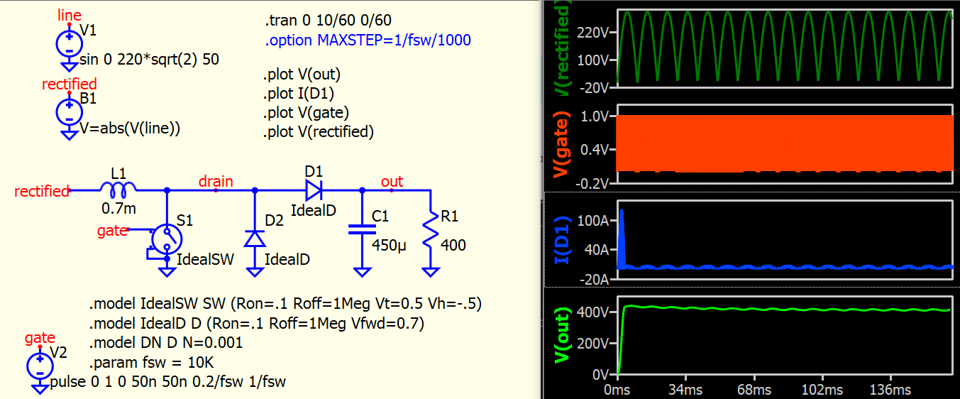
Setup a boost converter with 220Vac 50Hz rectified input but with fixed duty and frequency control for a quick verification. No problem with behavioral diode model. If change to default D or with N=0.001, a bit of current spike can observe at switching action but without negative current.
.model IdealD D (Ron=.1 Roff=1Meg Vfwd=0.7)
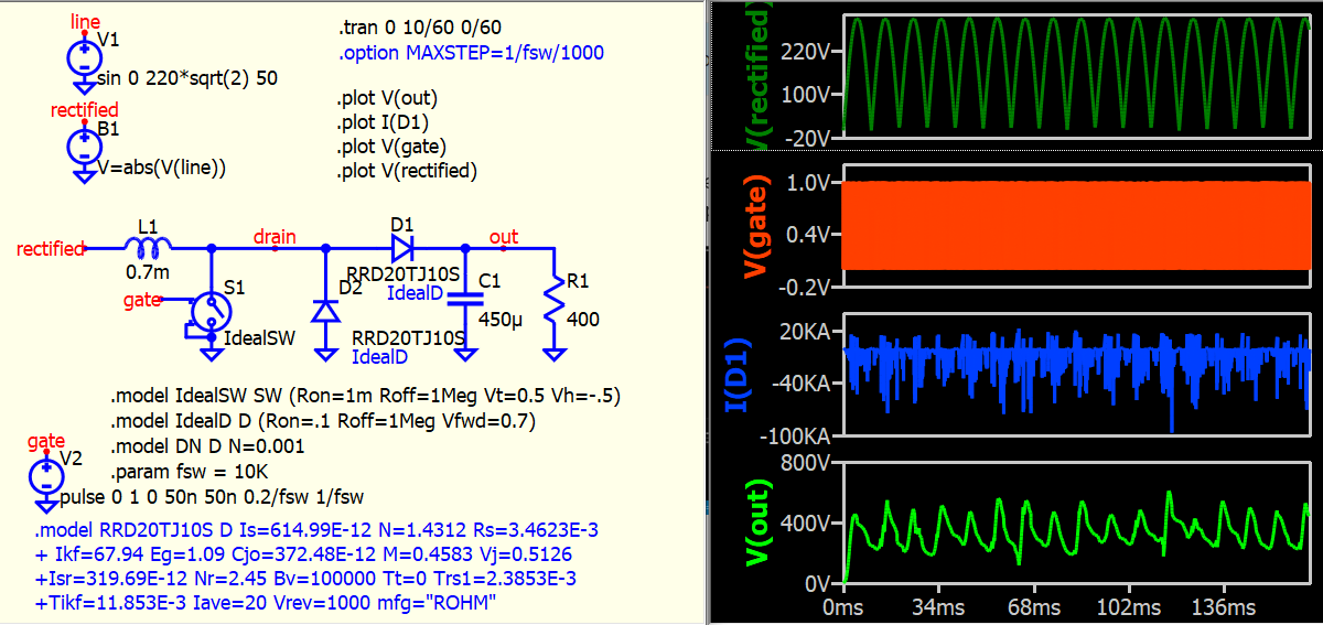
However, if I use diode from “selection guide”, for example, RRD20TJ10S, current can go crazy.
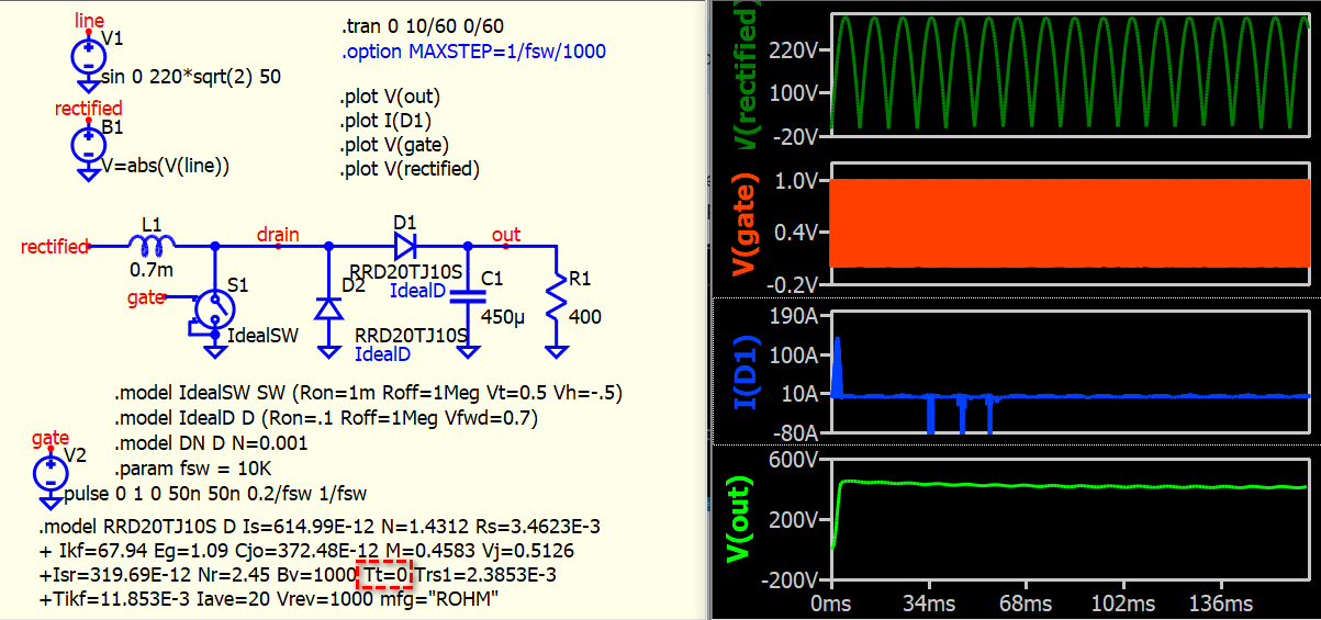
Qspice can simulate reverse recovery and breakdown characteristic of diode, if I force Tt=0 to disable reverse recovery, the chance of getting negative current is greatly reduced. I can further reduce negative spike by increase breakdown voltage Bv.
In general, a lot of aspect needs to be considered in PFC simulation, and gate drive pattern should follows input voltage, I just stop here and hope can give you more in-sight.
It seems you are using a sawtooth as input (pulse 0 210…) ? This is not something looks familiar in PFC setup.
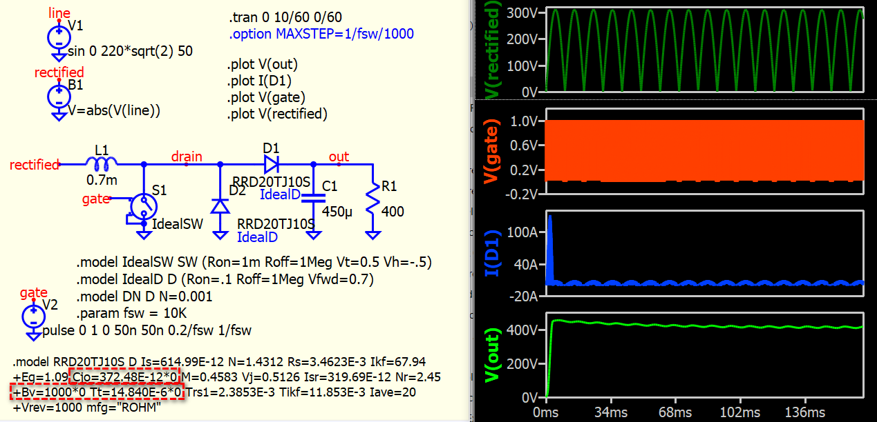
Cjo also affects reverse recovery.
In this example, force Cjo, Tt and Bv to 0, can almost eliminate all negative current spike in simulation with mfg model. Tt and Cjo play significant role in reverse recovery.
Try using the VP parameter for soft charge dissipation. I have found this parameter from the datasheet for some diodes. For example for 1N4007 Vp=30m.
For some pulse diodes, Vp has values of 60m to 90m. At least for which I have determined these parameters. You can use my file standard.dio. It is available on ltwiki.
dio.txt (426.2 KB)
Thank you so much for all your suggestions and findings with own circuits @KSKelvin and @bordodynov
I re-ran my simulation to test all your ideas but the exact issue that I had (several normal diode turn offs with expected reverse recovery then unexpected reverse recovery - many microseconds and several Amps of current with simulation points) but it has been fixed in a QSpice update. My colleague didn’t do the update (and it still simulates on his computer the same as the original plot from this post) so I’ve narrowed it down to being fixed between the following revisions:

Some general notes:
- I used a sawtooth just to show the issue in a linear way
- I typed the wrong word when I said “ideal diode” - I actually meant “default diode” - sorry for the confusion there but great to see use of an ideal diode as a comparison
- I wasn’t trying to eliminate reverse recovery as this is a normal part of performance but it is very interesting you also had issues when simulating a PFC and more importantly what you did to improve it
- From your findings it seems to be best to use an ideal diode to ensure these type of simulations behave until reverse recovery/capacitance etc is specifically required
Thanks again for taking the time to look into this.