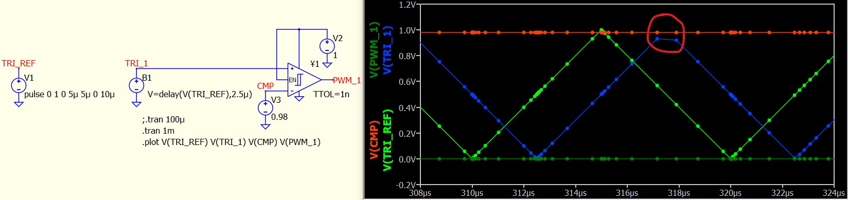
I’m wanting multiple PWMs that can be phase shifted and duty cycle adjustable during simulation. I used a voltage source to generate a reference triangle wave, behavioral sources, and Schmitt triggers to achieve this. Unfortunately, when the duty cycle is high (0.98 and higher) it doesn’t increase the number of points at the top of the behavioral source triangle wave(s), and it fails to trigger the Schmitt trigger(s). Below is a cutdown/simplified version to show the issue:
The simulation time is relatively long and the issue can be fixed by reducing the simulation time (not desirable as in the full version I want to close the loop on a SMPS with load changes etc) and/or setting the max step time to a value in the ns range (not desirable either as increases the execution time too much in the full version)
TTOL fixed a timing issue on the Schmitt trigger but I can’t seem to find a similar feature on the behavioral source
Adding “z” into the delay function doesn’t appear to fix the issue
Triangle waves (instead of sawtooths) are used as I want centre aligned phase shifted PWMs
I simulated the same circuit in LTSpice and it doesn’t seem to have this issue (or the other issue I posted: Diode sometimes not turning off )
Good suggestion but I want to adjust the phase shifts between sources (and duty cycles of each) during run time. In my cutdown/simplified example, I can change the simulation to vary the “CMP” net and/or the delay in the behavioral source from a varying net or C block to provide closed loop control (of a SMPS for example) - I just used fixed values in my example to simplify the circuit to show the issue.
My understanding is that V-sources are evaluated before the simulation starts and can’t be adjusted during - do you know of a way they can be adjusted during simulation?
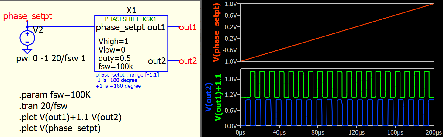
If you are ok to use delay(x,y) or delay(x,y,z) in your simulation, may be you can consider delay the pulse source directly. I setup a sub-circuit which can generate two pulses with phase change from -180 to 180 with an external voltage source from -1V to 1V. However, as you have multiple constraints in your post, I am not sure if can meet your requirements.
Thanks for your post @KSKelvin and nice sub-circuit
The issue seems to be with the delay function not forcing simulation points to represent the new waveform adequately (I also used this function). I recreated your implementation and it also fails to recreate the PWM on out2 at some phase angles if you change duty from 0.5 to >0.75 (or <0.25; more failures closer to 1 or 0) AND push the number of cycles up from 20 to 2000 in both places (I need at least this much simulation time in my full implementation):
I downloaded your schematic and replicated my results - you just missed changing duty from 0.5 to 0.75-0.99 (or .01-0.25). I used 0.75 for the post.
As mentioned, the issue seems to be extra simulation points are not generated when using the delay function, so with long simulation time (and without a min time step) waveform features of the delayed version can be missed.
I need to vary phase and duty to cover the entire range.
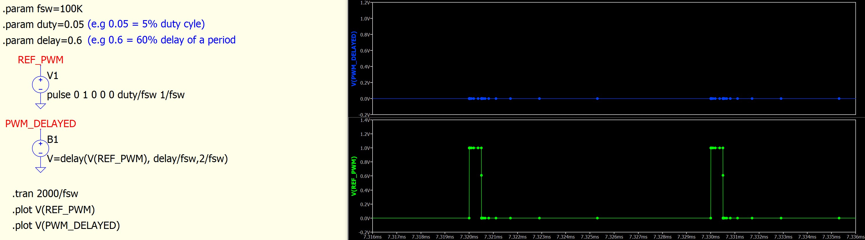
I’ve included an even simpler version to show the issue (adjust duty and delay to get different results). I’ve zoomed up on a couple of pulses and as you can see there no simulation points at the time where the delayed version should be so it is not generated:
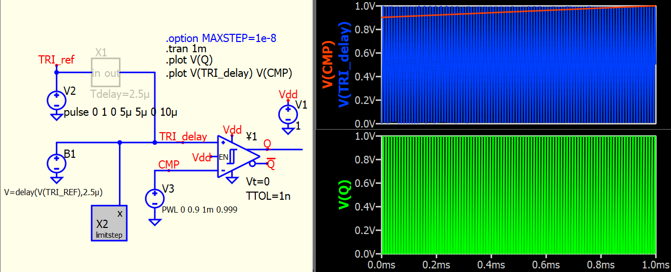
@davidrudd Just realized that there is a trick in controlling the timestep which can help resolve using delay function in your example.
Let first describe the problem. Qspice simulates in adaptive timestep, and behavioral source with a delay formula not necessary to follow its input signal timestep. This is observed in your first message in this post.
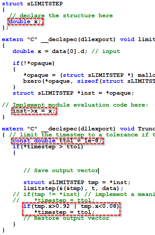
Therefore, the trick is to limit timestep when delayed signal approaches its corner, and .DLL offers Trunc() which can limit timestep. In this example, a .dll block is used to reduce timestep to 1e-8 when delayed signal > 0.92V and < 0.08V, which help to ensure delayed signal is fully reassembled.
Looks like a good work around - thanks @KSKelvin.
Great thinking and will give it a try soon
Thanks also documenting to exact code you used - appreciated.