We have been using MDEK kit. We have six anchors installed in a rectangular space of 8mx3m. Anchors are installed at a height of around 2.2meters. I have a tag at ground level (with clear LOS to all the anchors) placed vertically. We get x,y location of the tag from raspberry pi. After that we rotate the tag 180 degrees (ex…if the led lights on the tag are facing me, i rotate in such a way that the led lights on the tag are away from me) and measure the x,y location of the tag. I expect that x,y location in both cases are very close. Sometimes, I see the x,y locations before and after rotation are apart by >40cm. We have not changed anchor locations. Is it possible to explain this behaviour?
Yes. Unfortunately the only reasonably concise explanation is that RF signal propagation is complicated.
Any metallic materials (including circuit boards) within ~40 cm of the antenna is going to distort the patterns and result in asymmetries. Even non-metallic things like plastic housings will have an impact but these are far smaller than the effects of metallic items.
Thanks for the quick response. Do you mean any metallic within 40cm of the Anchor antenna? In our case, we have attached the anchors to the walls and cupboards. Only metallic things that i can think of the steel inside the wall and door handlers for cupboards. Would they make any difference? Tag is just rotated 180 degrees at the same place and not moved. Is there a way we can make this predictable?
Since you are seeing this as you rotate the tag without moving the effects you are seeing will be mostly due to the tag.
The best way to see if you are getting an effect from the anchors antennas is to walk in a straight line parallel to the edge of your test area and see if you get a straight line or a curve.
Just the tag/anchor circuit boards on their own will add a distortion. You must be getting power to them, that requires batteries and/or cables. If they are close to the antenna that’s another thing having an effect.
Where is the raspberry pi relative to the tag antenna?
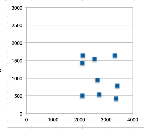
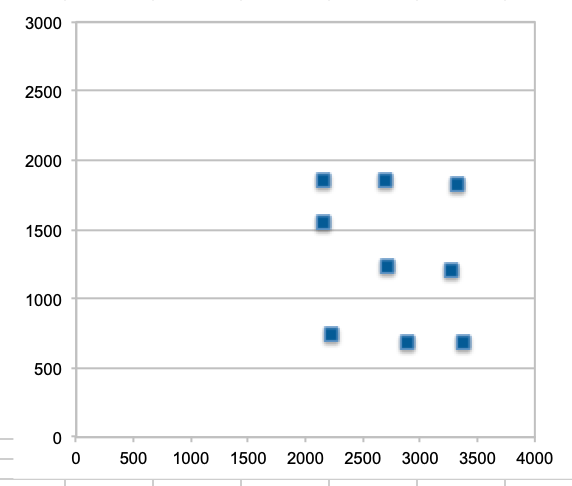
Thanks. We had done some experiments at few locations within the test area. I have attached two images. One is where the leds on the tag facing me and the other is where leds on the tag is away from me. Each point in the image is an average of 100 tag readings. Tags are placed exactly at the same location in both cases. (60.5cm apart horizontally and vertically almost parallel to x&y axes). In one of the images/experiment where leds on the tag is facing me, points are not quite in a straight line (or the other case where leds are facing away from me). RPi is on the ground level same as tag. RPi is 10-15cm away from the tag always on the side where the usb connector is.
Have you verified that you get the same results if you move things a little up off the floor? e.g. put it all on a cardboard box.
Generally being close to the ground is bad from an RF point of view.
Other than that the obvious but tricky thing to try is moving the antennas away from everything else, ideally including the electronics driving the antenna.
Hello Andy, If we increase the height by 30cm, readings become worse at certain places. But, if we increase the height to a meter, then the readings look better. Why would this happen? Would reflections confuse the tag?
We will try moving anchors away from any metal. Tags still needs to be connected RPi, but will try to use a long cable.
Ground bounce is certainly going to have an impact. At that height you’re going to hit a lot of nulls where the ground reflection is out of phase with the direct signal and so significantly reduces the signal strength.
Thanks Andy. What would be the optimal height to have the tags? Do you expect more error at the edge of area of interest compared to the centre? If so, is it due to the triangulation techniques used or any other reason?
Optimal height will depend on the distances between the tags and anchors.
I’d expect more errors at the edge of the space for two reasons:
The antenna patterns of the anchors aren’t uniform and they will generally be facing into the centre of the area which means away from the centre you are away from the angle they were calibrated at.
Secondly the geometry of the system will be worse, right on the wall you’ll only have anchors on one side, just like GPS or other positioning systems the more variety in the direction of your reference points the better your output accuracy. That’s just how the maths works out.
I’m not an expert on this sort of thing, I just know what I’ve found works and doesn’t work for my own applications.
Hi,
The effects of certain antennae close to the floor or wall are described in Application note APS006 channel effect on range accuracy , section 3.4.2 Multipath due to ground-bounce. eg it describes that it might be hard to conclude if a path is direct path or not, as signals nearly arrive at the same time at the receiver when they’re to close (<30cm) from the floor or wall.
With certain antenna I mean the antennae delivered with TREK/EVK or the ones on the DWM1000 or DWM1001. These antennae are omni directional and so radiating on both sides of the antenna, see data sheets .
A more directional antenna would probably be suitable.
For some background on antennae , see our Application note APS007 on Antenna Selection.
/Leo
With certain antenna I mean the antennae delivered with TREK/EVK or the ones on the DWM1000 or DWM1001. These antennae are omni directional and so radiating on both sides of the antenna, see data sheets.
Omnidirectional doesn’t mean identical characteristics in all directions just that you’ll get a result in all directions. I’ve measured 10 cm range discontinuities when rotating a system with an omnidirectional antenna.