Hi,
I just started using the evaluation board. And there is one doubt:
It is known that DWM 1002 Module has two DW 1000 chips or two tranceivers. In theory, it should also be able to serve as the tag with multiple antennas.
But in practice, this module is only used as the node/anchor and use PDOA to calculate the AOA with the phases received by the two antennas.
Therefore, I wonder whether the DWM 1002 Module can be used as the tag and if doable, how to modify the souce code or how to program to achieve the function.
It will be appreciated a lot if you can reply to me as soon as possible,
Thank you~
DWM1002 is dedicated PDOA node HW with dual antenna for PDoA measurement. If you want to turn it into tag, 100% you can, but i don’t understand why you have to do this as we have another dedicated HW DWM1003. If your question is how to port tag software to DWM1002, you need to modify code related to SPI, interrupts and GPIOs configuration, take a look at APS019_Driving_DW1000_from_8-bit_MCU.pdf under DW1000 - Qorvo.
Hop this helps.
Thanks for your prompt reply!
The reason why I want to make the PDOA node function as the tag instead of DWM 1003 Module is that I need a tag with multiple antennas and two antennas transmit one blink packet separately for my research project but unfortunately DWM 1003 Module is with single antenna. By the way, is there any Qorvo product which can satisfy the requirment ?
And in order to achieve the tag functionality using DWM 1002 Module, I plan to try not to modify the low-level code,instead, just modify the application level code. In theory, it is doable if we implement the tag mode by stripping and modifying the code of how to transmit a response packet from DWM 1002 Module because for the TWR process the node will transmit a response packet. In this way, I don’t know whether I should modify code related to SPI, interrupts and GPIOs configuration(I am majored in CS, Emmm,you know, have a very limited knowledge in low level hardware). Your advice seems to directly load the tag software code into the node so that we need to modify code related to SPI and so on?
And I will take a look into the document you mentioned.
Thanks for your help~
SDK for DWM1002 just can’t satisfy your requirements without changing node behaviors. You need to change NODE code or port one TAG code for DWM1002.
Check Qorvo UWB radio chips from links below, it looks like DW3220 is better options for you.
Qorvo search landing page - Qorvo
OK, thank you.
And I will try to use DWM 1002 first.
By the way, you mentioned that I need to modify the SDK. But I don’t know why. I thought SDK was just related to the platform and os and was independent of the source code of the node because they belong to two different folders…
And if I add and implement the tag_mode, just keeping the original architecture of DWM 1002, do you think I will have to modify the code related to SPI, interrupts and GPIOs configuration?
In DWM1002, MCU use 2 different SPI bus to connect to 2 DW1000s.
If you are going to do porting like using TAG source for DWM1002, you have to consider which SPI together with a few other GPIOs to use.
If you are using Node code, need to change Node behavior to match your expectation.
Thanks for your reply!
And in fact I didn’t see your reply until you sent it. Howerver, I thought it was better to reply after I organized my thoughts well. And now it is ripe time!
Yeah, I am using node code. I find it really an interesting work after I know and understand more and more about the code and the device!And now I have built and run the modified code successfully, though I am not very confident about my modification.
The general process is as follows:
I recorded my modification process and it will be very nice of you if you can go through it and it is better if you can give me some advice.
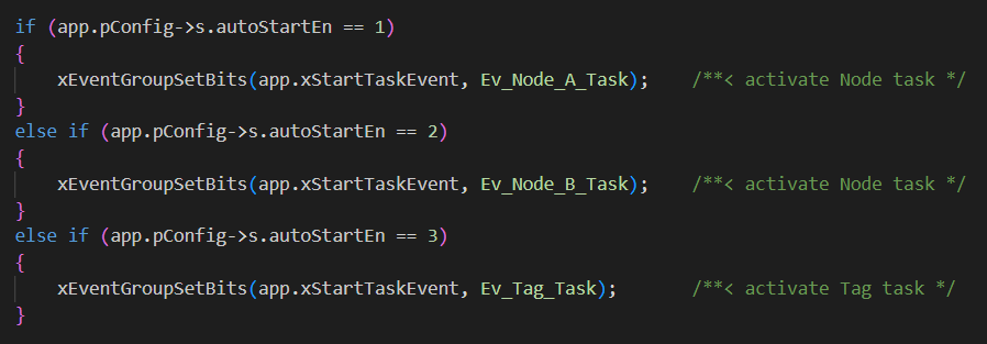
- I obseve that there is a declaration of the Ev_Tag_Task which is not used in node module and it is related to the event bit, as the following figure shows
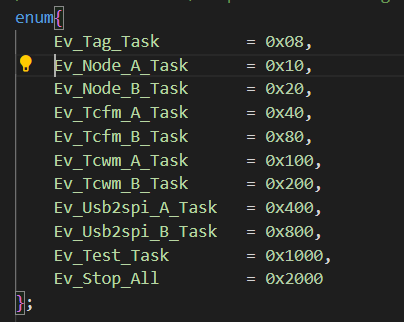
Therfore, what I have done here is to add the eventBit(Additionaly, I also need to modify the cmd to achieve the mode switch) and set the run-time parameter s.autoStartEn be 3 for Ev_Tag_Task if I want to activate the tag task instead of the node task after reset/power-on(I am confident that this is doable by passing a AOTO 3, what do you think of it?)
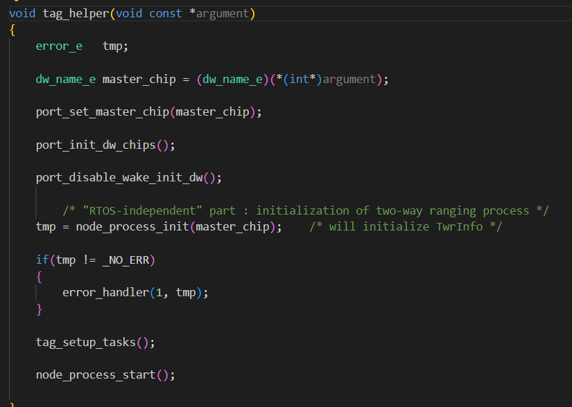
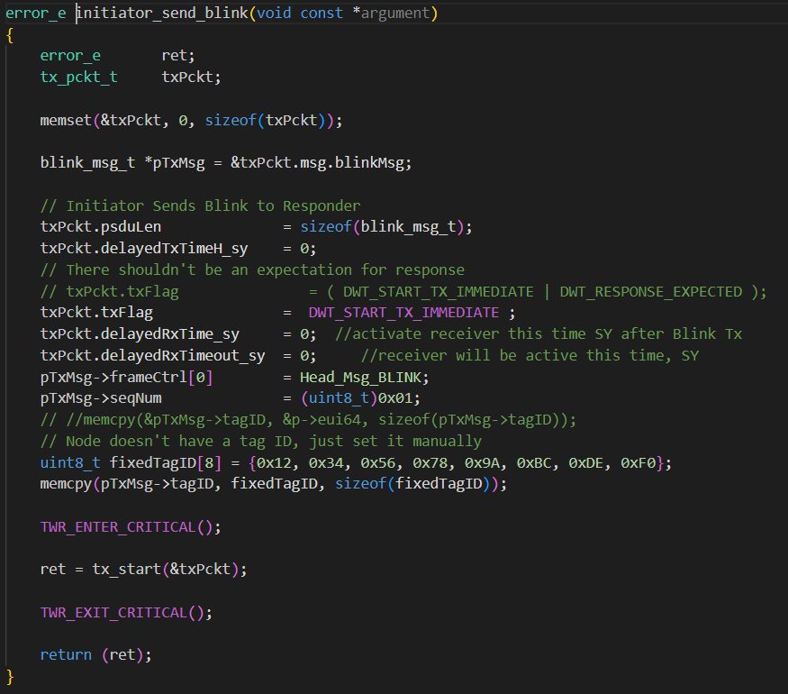
2.After that, I added and implemented the sending-blink functionality in function tag_helper() when the case is Ev_Tag_Task
3.For tag_helper() this function, I remained the basic strcture of the node, including the choice of the master chips and initiation of chips, disable_wake_init, initialization of two-way ranging process and node_process_start() which is to enable_dw1000_irq.
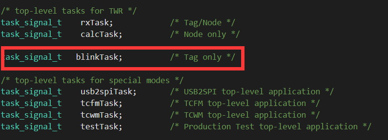
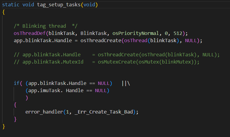
4.What I modified in helper function was about the setup of tasks.
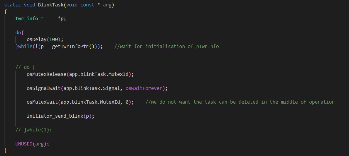
I defined the task signal the thread–blinkTask
- The core code is initiator_send_blink in function BlinkTask(). In initiator_send_blink, I define and instantialte the blink packet to be transmitted. And then call the function tx_start to send the packet(In addition, I need to set different SPI for different chips in tx_start in order to achieve the multiple antenna transmissions)
