Why I(C1) is not the same as I(C2)?
Why I(R1) is not the same as I(R2)?
(in terms of magnitude and phase values for both at 0.159 Hz)
I(C2) and I(R2) are the correct values.
See Draft4 schematic Draft4.qsch (9.3 KB)
and math calculation TEST.pdf (129.1 KB)
It seems that also LTspice has problem with this…
As I cannot upload the LTspice schematic I will attached a pdf file with results from LTspice: LTspice_results_Draft4_circuit.pdf (670.0 KB)
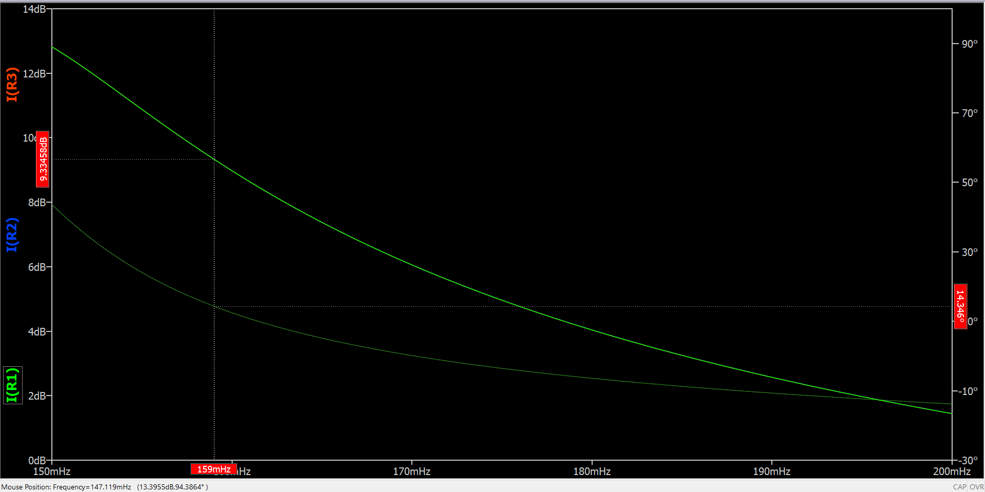
Yes, but this does not solve the stated problem. It is the same result as I got from LTspice and the same problem. Look at the phase of I(R1) = -75.57 deg vs the phase of I(R2) = 14.38 deg at 159mHz. Why?
If we make this difference 90 deg - 75.58 deg = 14.4 deg, we get the correct phase and also it is the phase obtained with math.
And If we plot -I(R1) = 104 deg, thus If we make the difference 104 deg - 90 deg = 14 deg, and is the same as summing 90 deg + 14 deg = 104 deg.
If we look at math results for I2(=I(12R)) = 12/(4-j) = 2.824+0.706j. So, there should be no problem in calculating the phase of this complex number 2.824+0.706j because the real part and imaginary part of this complex number are positive values (we are in first quadrant) and therefore no other addition/subtraction (like ±90 deg, or ±180 deg) should not be employed in phase of the final result of this complex number.
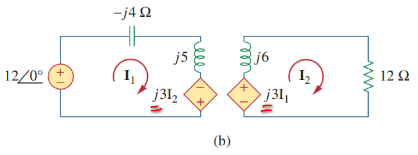
The value results for I1/I(C1) and I2/I(R1) are calculated based on the schematic with arbitrary behavioral voltage sources (BV sources) if you look in the TEST.pdf, so therefore I(C1) needs to be equal with I(C2) I(C1)=I(C2) and I(R1) needs to be equal with I(R2) I(R1)=I(R2) in terms of magnitude and phase values due to the fact that the two schematics are equivalent.
And then If we run the simulation with this: .ac lin 100 0.159 1 and plot in the same plot plane I(C1) vs I(C2) and I(R1) vs I(R2).
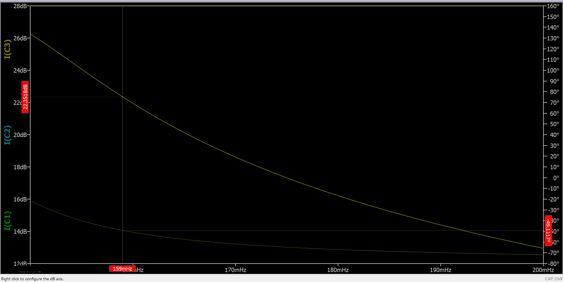
We will see that at frequency of 0.159Hz this is happening magnitude(I(C1))=magnitude(I(C2)) and phase(I(C1)) = phase(I(C2)) and magnitude(I(R1))=magnitude(I(R2)) but phase(I(R1)) different than phase(I(R2)), but then the each two corresponding graphs are different (both in magnitude and phase) at frequency > 0.159Hz. I am wondering why? If I plot I(C1) vs I(C2) and I(R1) vs I(R2) in the same plot plan then the each two corresponding graphs should not be the same, so they overlap each other on the entire frequency range? Or?
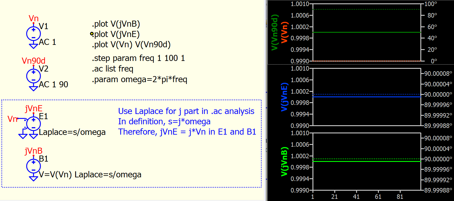
Have you consider phase of your Behavorial source?
Currently you are only implementing 3*I2 or 3*I1 but not j3*I2 or j3*I1.
But is it common to use spice to simulate phasor math?
Then how to implement this with j in front în simulation, but having in mind also that when ploting in the same plot plane I(C1) vs I(C2) and I(R1) vs I(R2) to be able to see the each two correspoding graphs to overlap each other on the entire frequency range, not only at a specific value of frequency (0.159Hz), due to the fact that the two schematics needs to have the same results as they are equivalent
I just not sure if spice is a tool for this kind of math.
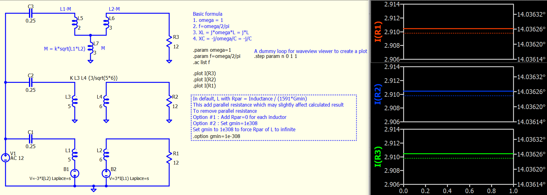
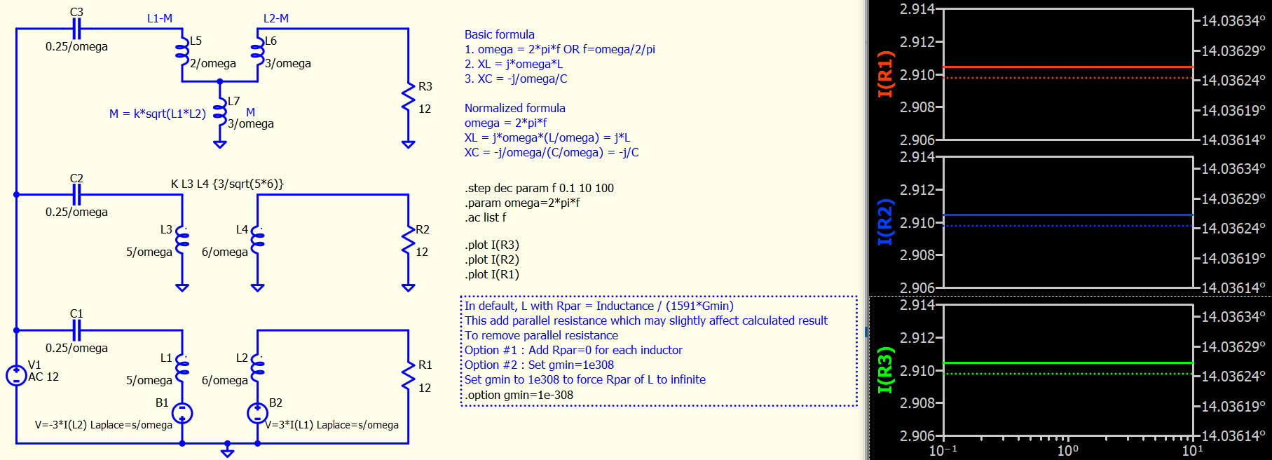
For inductor, its XL = 2*pi*f*L, and in phasor, e.g. j5 is something frequency independent. It seems what you are trying to do is to calculate by assuming omege = 2*pi*f = 1, which you should only consider thing can match at freq = 1/2/pi and not other frequency, as you are not at 2*pi*f=1, you won’t get XL=j5 or j6 anymore.
Furthermore, how to handle a dependent source with imaginary part is something I never consider. Because this is the first time I see someone trying to simulate a phasor math in this way, that why I wonder if spice is a proper tool for this.
Yes, spice can simulate mutual inductance. But the problem is dependent source with phase in .ac analysis, is something I cannot recall I saw about. May be people in this forum has idea for that.
@Cornel This is for you to consider for replicate your phasor math which originally in TEST.pdf is frequency independent.
Option #1 : Just simulate everything at omega=1. The only problem is that .ac list at a single frequency cannot generate a plot in waveform viewer (you can still get data by export in waveform viewer in text format). Therefore, a dummy loop is add to help generating a plot
Option #2 : Normalize all devices equation to give same real or imaginary number at any given frequency
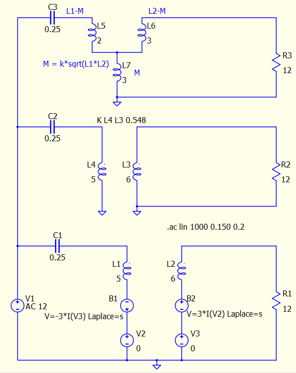
In both cases, as you are simulating inductance with relatively huge value, its parallel resistor effect can contribute to the math, as in default all inductor is parallel with a Rpar = Inductance / (1591*Gmin). So, you can see I add a .option gmin=1e-308 to remove its effect. You can also manually add a 2nd attribute to Inductor with Rpar=0 to force Rpar to infinite. Just gmin is quicker in this case and have no side effect.
@KSKelvin I noticed that you removed the normal voltage sources of 0V with which we read the current through each braches, and instead you read the inductor currents I(L1) and I(L2) in behavioural sources. Is good to do this way? Or is better to use normal voltage sources with 0V, and read the current through this sources for further calculations? I mean from general point of view.
L1 and V2 are in series and their current are identical where I(L1)=I(V2).
It depends how your circuit is. The advantage of 0V voltage is that you can be sure +ve current represent current flow from + to - terminal. But just call to use I(L1), you must be sure which node is first and which node is second to determine current direction.
I remove the 0V voltage source only for simplicity for this schematic.
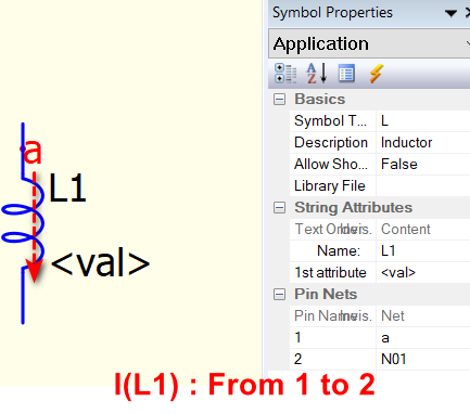
Current of R/C/L is always flow from Pin 1 to 2. To view pin net, you can right click on component, Show Symbol Properties, and you can read its Pin and Net relationship.
If you name a net, this will be more easy to identify which terminal is Pin 1 or 2.
Another way is View > Netlist. Fundamental of spice is to simulate a netlist, which is text syntax. The GUI is only to help converting a schematic to netlist. So, to understand spice completely, learning to read netlist is an essential step.
I know simulation software may offer current direction when hover device for current measurement. But it seems this feature is not in Qspice so far. Therefore, best way is to learn something how syntax work.