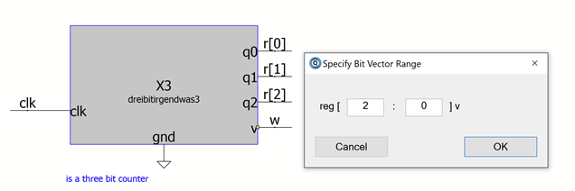
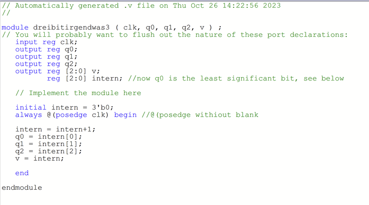
Hello, the circuit shown is a simple 3 bit counter. I created q0, q1, and q2 in order to display the single bits of the three bit ‘reg [2:0] intern’ (see verilog interface).
‘v’ had been set to an output type three bit bus when creating the symbol (DLL).
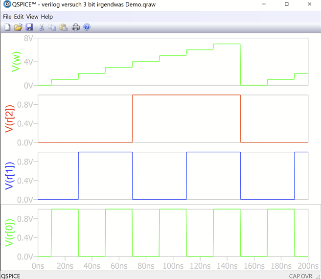
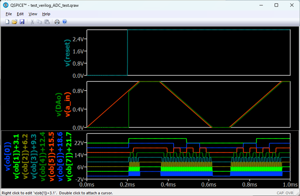
So in the waveform viewer the signal connected to the pin v becomes a staircase.
Would there be a smarter way to transport the single bits of ‘reg [2:0] intern’ to the top level QSPICE schematic, so they can be processed individually or displayed in the waveform viewer?
In addition to my last post, I have one more note to share.
Whenever I changed any port data type, I recreated the ‘Verilog .DLL C++ main template’.
Verilog sources are converted to ‘C/C++’ sources by ‘Verilator’, so it seems that we must update not only the Verilog source but also the ‘Verilog .DLL C++ main’.
I have found the same thing. Since I don’t write in C++, I made a batch file to delete all of the C++ output of the verilator when needed. That and creating a new port declaration for the verilog seems every time there is a new port makes everything work nicely.