Hi. I implemented a closed loop system using a digital controller- by using a C block. This circuit is not a SMPS. I’m trying to extract a bode plot using the bode command. Is it even possible with the digital controller? Thank you.
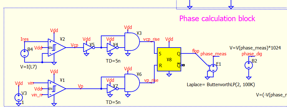
In addition- If I’m using digital gates as part of my feedback loop (to calculate phase between two signals)- will the bode command work? Here is the logic circuit I’m talking about:
… @RDunn and I had a project, implemented a C++ PID controller in Qspice and ran .bode test results. You need to have a system which is close-loop stable before you run .bode. You also need to determine where to put the perturbating source such that your .bode can work.
C++ PID Controller for Qspice (Community Project) - QSPICE - Qorvo Tech Forum
If you need more information about setting up .bode, you can refer to this post
Frequency Response Analysis (.bode) Study Guide - QSPICE - Qorvo Tech Forum
Ok thanks. good to see that it’s possible. I tried tio put the perturbation between the measurement to the error calculation( in analogy to the classic location for measuring LG). But the result of the bode plot is nonsense. I don’t use switching in my circuit. But my sensor and control is very non-linear. Can the bode command handle circuit like the phase detector I created above?
