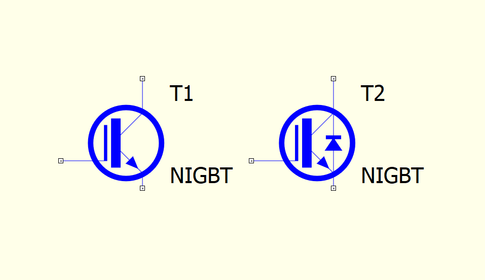
Some symbols for KiCad 5 converted as a test. As bitmap from clipboard:
After printing to PDF and changing line width with Inkscape:

SVG images are disabed in this forum, so PDF instead:
0-050098-11.edited.pdf (19.8 KB)
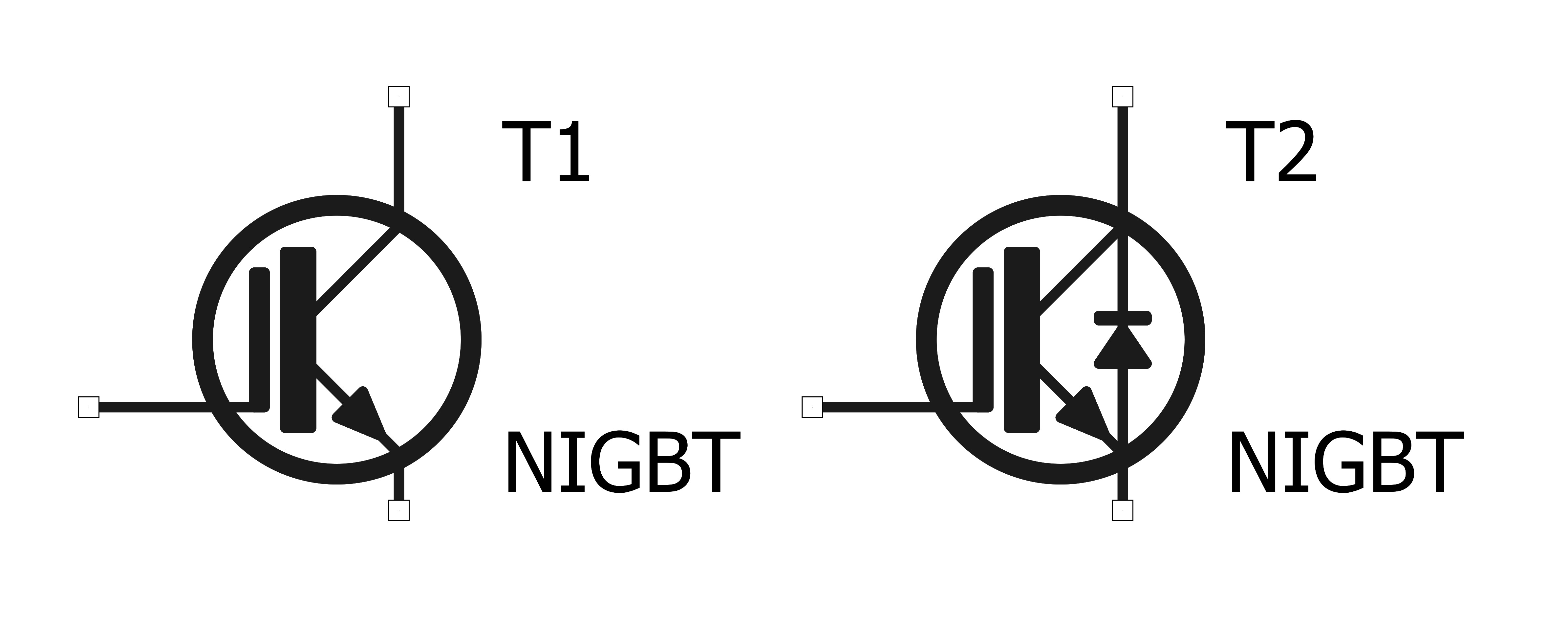
Some symbols for KiCad 5 converted as a test. As bitmap from clipboard:
After printing to PDF and changing line width with Inkscape:
SVG images are disabed in this forum, so PDF instead:
0-050098-11.edited.pdf (19.8 KB)
I believe Qspice is designed for calculations. That’s why R-LDR symbols without a control pin are puzzling. In LTspice I have a symbol of such a device with three pins. On the third pin I apply a voltage equal to the illumination of the light-sensitive pad.
Thanks for your work.
It is necessary to add more elements. For example: photodiode, IGBT transistor, Optocoupler.
Bordodynov.
Yes, the LDR is just included for its distinctive looks (compared to other standards) and not for its functionality (it’s just a regular R; the photo diode uses subckts from Analog so I didn’t include it yet). The idea is to provide some over-specified (retro style) symbols that can be easily modified (by removing or hiding unnecessary parts like envelopes or indicators) or composed from several symbols.
If get around, I’ll eventually also convert my more standard IEC/IEEE style symbols for LTspice/KiCad5 to QSPICE (they use 1.0 font size and fit better with the Builtin Symbols, but LTspice uses 160 dpi while KiCad5/QSPICE use 1000 dpi and KiCad has more features like filled polygons or UTF-8, so there is some adapting and working-around necessary.).
BTW, I recently came across this databook. Any of your integrated circuits?
Yeah. Five KP1533s. I’ve been doing reverse engineering. I reproduced the schematic and topology of the chips from the photo. It wasn’t a literal copy. I used a completely different topology for the output transistors. I was glad that I applied a more optimal emitter - narrower. But six months later, a new chip arrived with the A suffix and it had a narrower emitter on the output transistors than my transistors. It seems that the designers of microcircuits experimentally selected the size. I did so with determining the optimum area of the Schottky diode. Still, we have a different technological process of chip manufacturing.
For reference, here are my symbols that were designed for LTspice (the SVG files show how the symbols were supposed to look like):
I wish QSPICE and LTspice supported the exporting of a schematic in SVG file format.
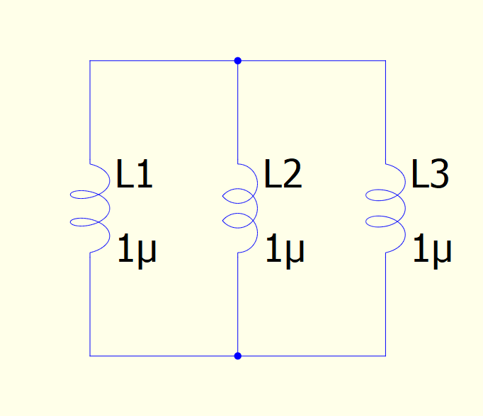
Adapted IEEE variant of builtin inductor symbol:
«symbol L
  «type: L»
  «description: Inductor»
  «shorted pins: false»
  «line (0,200) (0,180) 0 0 0x1000000 -1 -1»
  «line (0,-200) (0,-180) 0 0 0x1000000 -1 -1»
  «arc3p (0,-180) (-62,-50) (0,-100) 0 0 0x1000000 -1 -1»
  «arc3p (-62,-50) (-62,50) (0,0) 0 0 0x1000000 -1 -1»
  «arc3p (-62,50) (0,180) (0,100) 0 0 0x1000000 -1 -1»
  «text (100,150) 1 7 0 0x1000000 -1 -1 "L"»
  «text (100,-150) 1 7 0 0x1000000 -1 -1 "<val>"»
  «pin (0,200) (0,0) 1 0 0 0x0 -1 "1"»
  «pin (0,-200) (0,0) 1 0 0 0x0 -1 "2"»
»
Conventional orthographic projection of helix:
«symbol L
  «type: L»
  «description: Inductor»
  «shorted pins: false»
  «line (0,200) (0,180) 0 0 0x1000000 -1 -1»
  «line (0,-200) (0,-180) 0 0 0x1000000 -1 -1»
  «arc (-140,-183) (80,-31) (0,-180) (-30,-31) 0 0 0 0x1000000 -1 -1»
  «arc (-80,-31) (20,-76) (-30,-31) (-30,-76) 0 0 0 0x1000000 -1 -1»
  «arc (-140,76) (80,-76) (-30,-76) (-30,76) 0 0 0 0x1000000 -1 -1»
  «arc (-80,31) (20,76) (-30,76) (-30,31) 0 0 0 0x1000000 -1 -1»
  «arc (-140,183) (80,31) (-30,31) (0,180) 0 0 0 0x1000000 -1 -1»
  «text (100,150) 1 7 0 0x1000000 -1 -1 "L"»
  «text (100,-150) 1 7 0 0x1000000 -1 -1 "<val>"»
  «pin (0,200) (0,0) 1 0 0 0x0 -1 "1"»
  «pin (0,-200) (0,0) 1 0 0 0x0 -1 "2"»
»
Same equation, different coefficient (k).
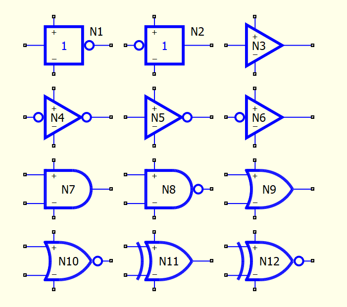
Added a few gates to qspice-symbols:
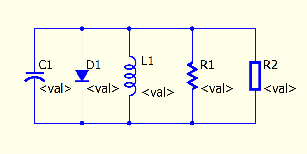
Attempt at Radio Electronics (News) style C, D, L, R symbols (also in repository):
C.qsym (828 Bytes)
D.qsym (525 Bytes) D-alt.qsym (515 Bytes)
L.qsym (1.3 KB)
R.qsym (2.2 KB) R-alt.qsym (640 Bytes)
Very Nice!
For outsiders that visit each of your symbol repository directories on gitlab,
it would be very useful to have a PNG file at the top of each directory that
shows the entire collection in one image, such as !GALLERY!.png
Thanks in advance!
Currently, there are only a few small files, so I think it’s reasonable to download or clone the whole repository and use Add a symbol directory in QSPICE or use the Preview pane in Windows File Explorer (if QSPICE was installed as Admin).
Ideally, I would add them to the repository as SVGs for preview but the conversion would have to be automatic…
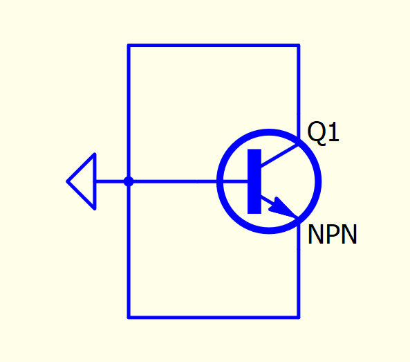
R-E style transistors seem to be another pain in QSPICE – not sure I’ll do them all…
As with the Elektuur style, the line width of the wires was 0.25mm or 10mil in the original, and thick lines were that ×2 (some ×√2 or ×√8). In these Radio-Electronics style symbols, however, all thick lines are made by 2 parallel (size 0) default-width lines with a third fixed-width line in between as fill, to better accommodate the zig-zag resistors. That means the symbols get bolder on the screen (only, and depending on the zoom level) when CAD Line Thickness is increased in preferences.
«symbol Q-BJT-NPN
  «type: QN»
  «description: bipolar junction transistor (BJT): NPN»
  «library file: NPN.txt»
  «shorted pins: false»
  «line (100,200) (100,110) +00 0 0x1000000 -1 -1»
  «line (100,110) (-19,40) +00 0 0x1000000 -1 -1»
  «line (-200,0) (-41,0) +00 0 0x1000000 -1 -1»
  «line (100,-200) (100,-110) +00 0 0x1000000 -1 -1»
  «line (100,-110) (-19,-40) +00 0 0x1000000 -1 -1»
  «line (83,-100) (35,-50) +00 0 0x1000000 -1 -1»
  «line (83,-100) (16,-82) +00 0 0x1000000 -1 -1»
  «rect (-45,90) (-15,-90) 0 +00 0 0x1000000 0x3000000 -1 0 -1»
  «ellipse (-132,145) (158,-145) 0 +10 0 0x1000000 0x1000000 -1 -1»
  «ellipse (-127,140) (153,-140) 0 +00 0 0x1000000 0x1000000 -1 -1»
  «ellipse (-137,150) (163,-150) 0 +00 0 0x1000000 0x1000000 -1 -1»
  «arc3p (22,-81) (37,-55) (-2,-50) +04 0 0x1000000 -1 -1»
  «arc3p (16,-82) (35,-50) (-2,-50) +00 0 0x1000000 -1 -1»
  «triangle (83,-100) (38,-54) (22,-83) +00 0 0x1000000 0x3000000 -1 -1»
  «triangle (83,-100) (35,-50) (35,-72) +00 0 0x1000000 0x3000000 -1 -1»
  «triangle (83,-100) (16,-82) (35,-72) +00 0 0x1000000 0x3000000 -1 -1»
  «text (125,150) 0.5 7 0 0x1000000 -1 -1 "Q"»
  «text (125,-150) 0.5 7 0 0x1000000 -1 -1 "NPN"»
  «pin (100,200) (0,0) 0.5 0 0 0x0 -1 "C"»
  «pin (-200,0) (0,0) 0.5 0 0 0x0 -1 "B"»
  «pin (100,-200) (0,0) 0.5 0 0 0x0 -1 "E"»
»
«symbol Q-BJT-PNP
  «type: QP»
  «description: bipolar junction transistor (BJT): PNP»
  «library file: PNP.txt»
  «shorted pins: false»
  «line (100,200) (100,110) +00 0 0x1000000 -1 -1»
  «line (100,110) (-19,40) +00 0 0x1000000 -1 -1»
  «line (-200,0) (-41,0) +00 0 0x1000000 -1 -1»
  «line (100,-200) (100,-110) +00 0 0x1000000 -1 -1»
  «line (100,-110) (-19,-40) +00 0 0x1000000 -1 -1»
  «line (7,55) (55,105) +00 0 0x1000000 -1 -1»
  «line (7,55) (74,73) +00 0 0x1000000 -1 -1»
  «rect (-45,90) (-15,-90) 0 +00 0 0x1000000 0x3000000 -1 0 -1»
  «ellipse (-132,145) (158,-145) 0 +10 0 0x1000000 0x1000000 -1 -1»
  «ellipse (-127,140) (153,-140) 0 +00 0 0x1000000 0x1000000 -1 -1»
  «ellipse (-137,150) (163,-150) 0 +00 0 0x1000000 0x1000000 -1 -1»
  «arc3p (53,100) (68,74) (92,105) +04 0 0x1000000 -1 -1»
  «arc3p (55,105) (74,73) (90,104) +00 0 0x1000000 -1 -1»
  «arc3p (55,105) (74,73) (92,105) +00 0 0x1000000 -1 -1»
  «triangle (7,55) (52,101) (68,72) +00 0 0x1000000 0x3000000 -1 -1»
  «triangle (7,55) (55,105) (55,83) +00 0 0x1000000 0x3000000 -1 -1»
  «triangle (7,55) (74,73) (55,83) +00 0 0x1000000 0x3000000 -1 -1»
  «text (125,150) 0.5 7 0 0x1000000 -1 -1 "Q"»
  «text (125,-150) 0.5 7 0 0x1000000 -1 -1 "PNP"»
  «pin (100,-200) (0,0) 0.5 0 0 0x0 -1 "C"»
  «pin (-200,0) (0,0) 0.5 0 0 0x0 -1 "B"»
  «pin (100,200) (0,0) 0.5 0 0 0x0 -1 "E"»
»
I have uploaded two optoisolators to the files section of the groups.io group. They are in the Test Circuits folder included in the schematic that tests them. They are 4N25 and PC817.
Bruce108
In Symbol windows
Standard is minimum step by 50 per move (refer to status bar coordinate)
Hold Ctrl or Alt or Shift is minimum step by 10
Hold any two key (e.g. Ctrl+Alt, Ctrl+Shift, Alt+Shift) is minimum step by 5
Hold all three key (Ctrl+Alt+Shift) is step by 1
As I deleted my post by mistake, I am posting again:
Hi @mgyger, thanks for your hard work! So the symbols are pretty beautiful! So, let me have a question? How you do to handle with the grid? I was trying to do something similar as you made on Elektuur symbols of the Op Amp, which is, draw a triangle inside other triangle. But in my case, is a line on the side of the other line. But I’m not able. When I try to make it, the lines just follow the grid. Do you have some tip or software to help?
@KSKelvin Wow, thank you so much! You helped me a lot! I appreciate that.
QSpice is becoming my first option on simulation!
By the way, I didn’t know about Qorvo before.
QSpice. Besides a great software, it is becoming like a visit card to the Qorvo company.
Thanks! @KSKelvin’s way above is the simplest. I actually didn’t use the symbol editor because I’ve used a text editor with Windows/CP-1252 encoding to create the code directly (mostly copy/paste and modification, with some scripting), similar to when you right-click in the Symbol & IP Browser on a symbol and select Open a Copy as ASCII text.
Hello, Do you know how to change the font face on qspice ?