Hello,
I was wondering if anyone has come across any good spice models for 650V GaN FETs?
I looked for GaN system models but didn’t have any luck, and I tried the SPICE models for some Transphorm parts available here: High Voltage GaN Design Resources - Transphorm
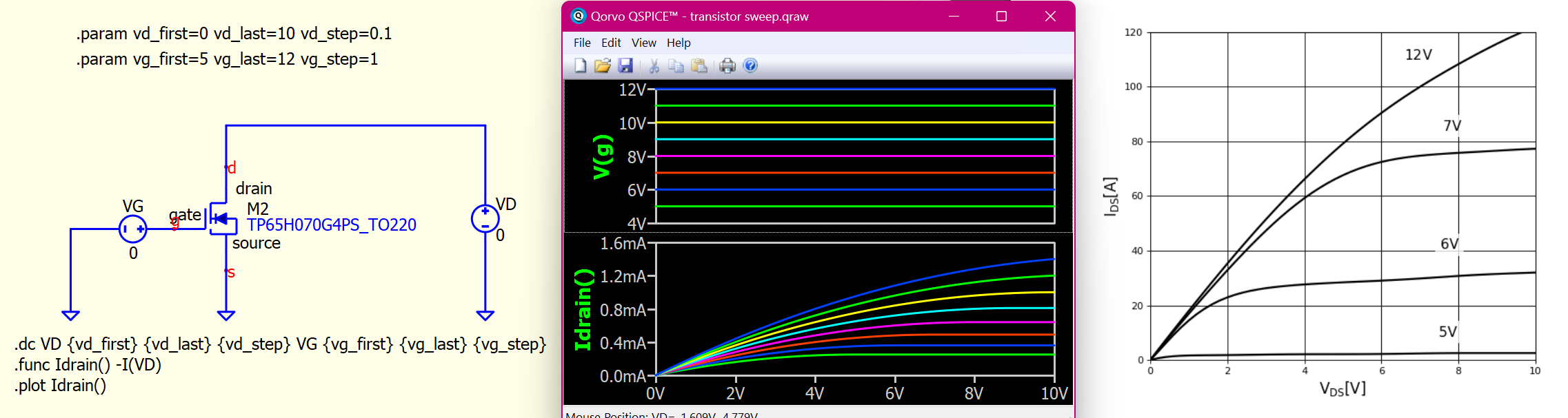
But all their simulations error out in LTspice (which I find ironic since they are LTspice files) and pulling the SPICE model over into Qspice gives results that don’t align at all to the data sheet. Maybe I’m not doing it right, but I did follow Mr. Engelhardt’s video.
SPICE file:
*************************************************************************
* ver 1.1, Jan 29, 2024, By Geetak Gupta, Nihal Singh @ Transphorm
*************************************************************************
* Level 1 model (L1T1)
*************************************************************************
* The model is an approximation of the device.
* The model may not show the true device performance under all conditions.
* The model only guarantees the accuracy of the key parameters (Ron, Ciss,
* Coss, Crss, Eoss, Qoss, and Qrr) in the current data sheet.
* Please refer to the current datasheet for the most up to date specifications
* of the device.
* Transphorm Inc. does not assume any liability arising from this use.
* Transphorm Inc. reserves the right to change models without prior notice.
*************************************************************************

.subckt TP65H070G4PS_TO220 drain gate source

.param fsat1={144} fsat2={8.5} fsat3={4.9}
.param frp1={0.55} frp2={1.33} frp3={6.35} frp4={0.25}
.param frev1={142} frev2={0.264} frev3={0.83}
.param fgd1={2.1} fgd2={1.05} fgd3={0.177}
.param fsd1={73} fsd2={45} fsd3={0.057}
.param fgs1={646}

Ls source 101 1n
Rls 101 S 0.01m
Lg gate 201 3n
Rlg 201 G 0.01m
Ld drain 301 1n
Rld 301 D 0.01m

Rgs G S 1e8
Rgd G D 1e8
Rds D S 1e8

Cgs G S {fgs1*1e-12}

Csd1 S 105 {fsd1*1e-12}
Csd2 S 105 Q = 1e-9*2*fsd2*((1/(1+exp(-fsd3*(x))))-0.5)
Rdss 105 D 4

Cgd1 G D {fgd1*1e-12}
Cgd2 G D Q = 1e-9*2*fgd2*((1/(1+exp(-fgd3*(x))))-0.5)

Rs S S1 0.1m
Rd D D1 0.1m
Rg G G1 0.1m

.func Idsat(t) if(V(G1,S1) < fsat3, 0, if ( V(G1,S1) < fsat2, fsat1*(V(G1,S1)-fsat3)/(fsat2-fsat3), fsat1))
.func Rp(t) (frp1*((1/(1+exp(frp2*(V(G1,S1)-frp3))))) + frp4)

bchnl D1 S1 I = {if ( V(G1,S1) > fsat3, 2*Idsat(time)*((1/(1+exp(-Rp(time)*V(D1,S1)))) - (0.5)), 0)}

bdiode D1 S1 I = {if ( V(D1,S1) < -frev3, -2*frev1*((1/(1+exp(-frev2*(abs(V(D1,S1))-frev3))))-0.5), 0)}

.ends TP65H070G4PS_TO220
If you take a look of your simulation output window, FET should be forced to default model and therefore, giving you a result completely different to datasheet. In short, you are not actually calling TP65H070G4PS_TO220 subckt to use.
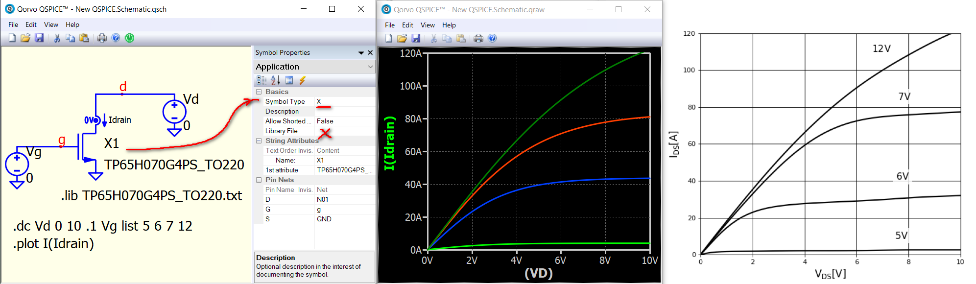
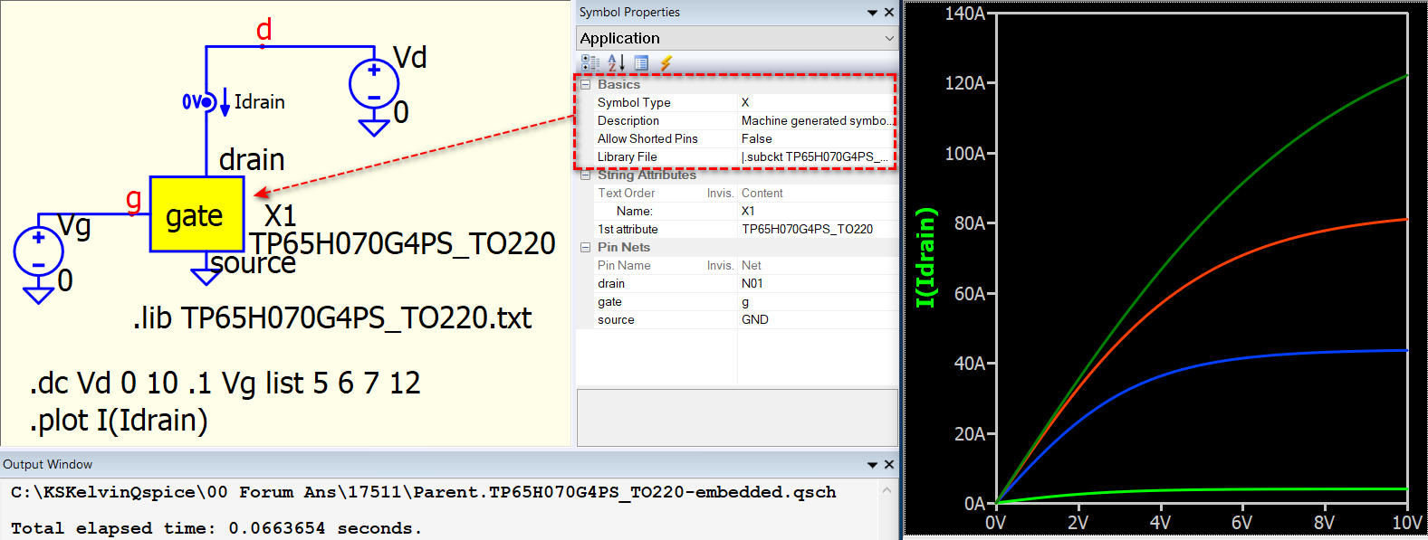
TP65H070G4PS_TO220 is a .subckt, which can only be called with symbol type X. This subckt is simple, as its pin arrangement is drain, gate and source, and we can simply take the NMOS symbol and convert it to symbol type X, without the need of creating a user symbol for it. Subckt doesn’t offer current probe at its terminal, we have to add 0V voltage source or resistor for current sense.
Parent.TP65H070G4PS_TO220.qsch (3.6 KB)
TP65H070G4PS_TO220.txt (2.0 KB)
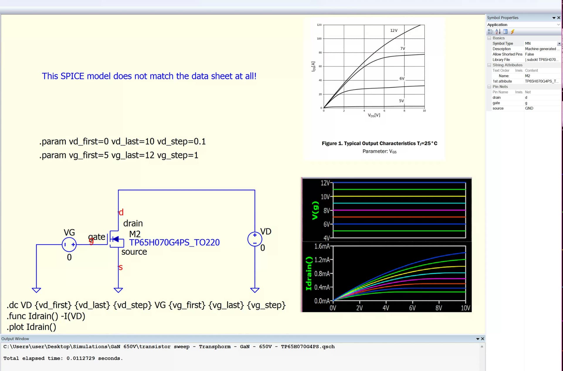
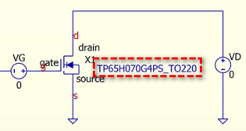
@KSKelvin Im super glad you are here keeping us all on track. I do not see any indication when I run the simulation that Qspice is NOT using the P65H070G4PS_TO220 subckt, see image:
Also, I would like to keep the file self contained so instead of calling the .lib I would like to keep the library file associated with the symbol (in the library field) if that is possible.
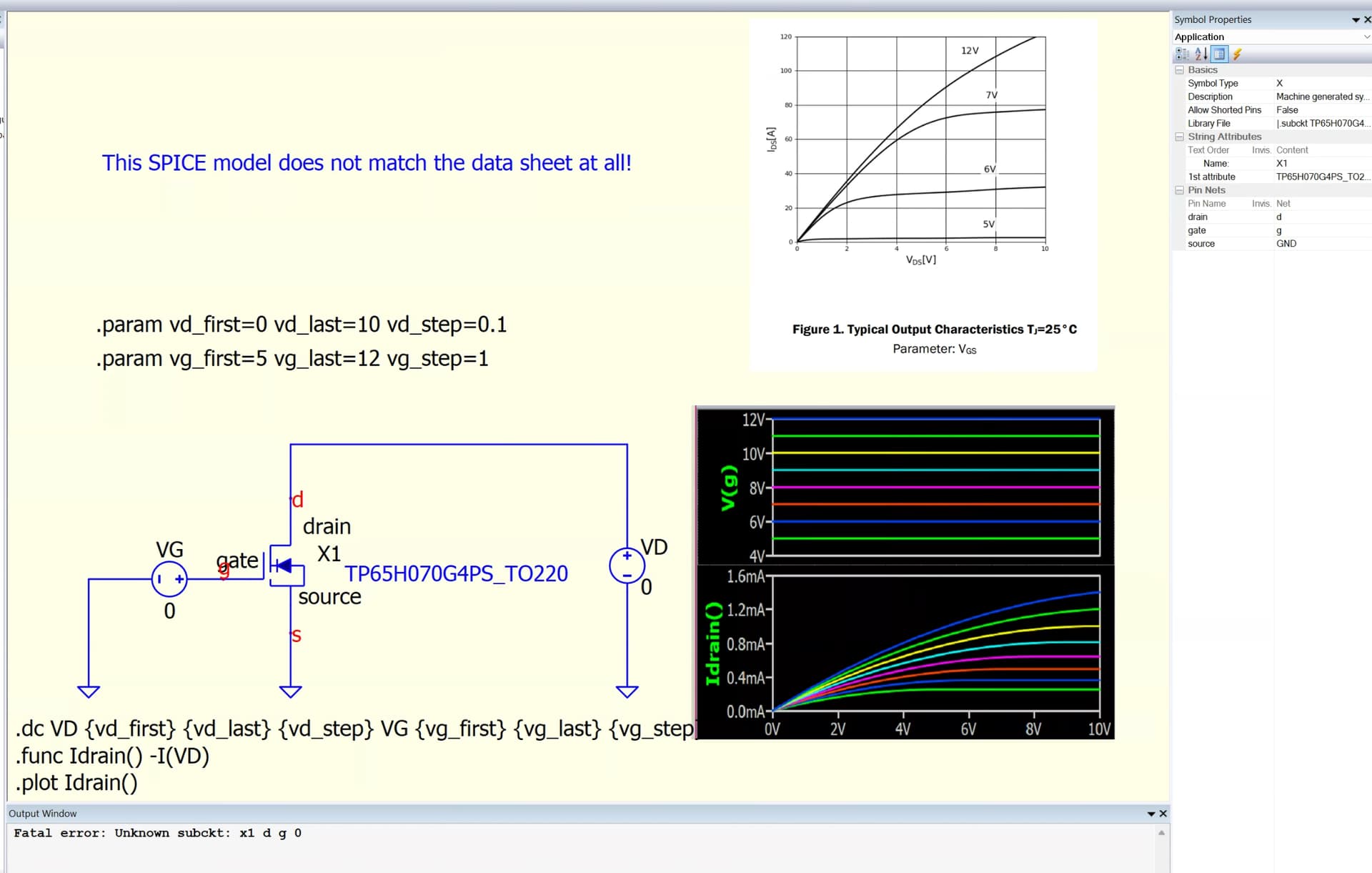
Changing the symbol to an “X” type results in the error seen below. Do I need to edit the library file to indicate X1? Or is the only way to do this to call the .lib file?
As far as I can tell I followed the “how to” video for importing .subckt into Qspice:
Qspice auto generated the symbol on import but I didn’t notice anything in the video indicating that I need a “X” device instead of whatever Qspice decided to import (a MN device in this case, which seems reasonable for this part) and the simulation then ran without error but gave the wrong results.
You mentioned that I should see some indication that qspice is using the default model, where would I see that?
Upload your .qsch.
Or go download my General Reference Guide and read part 2B, 2C and 2D about symbol for subckt.
I believe somewhere you made a mistake as you shouldn’t have an embedded symbol with .subckt in library file but Symbol Type as MN.
This is what expected if you follow “how to” video by Mike.
Parent.TP65H070G4PS_TO220-embedded.qsch (4.5 KB)
I noticed that the first attribute in your symbol is a comment based on your screen capture, which means that you haven’t actually provided any model name to be called. In the automatic symbol generation process, it would not include a comment like that, so it seems that you may have mistakenly commented it. As you commented the model name, behavior without any indication is somehow related to that. It is not always easy to identify the problem without the inclusion of the .qsch file in the question.
The symbol type X is for .subckt in SPICE. People with a background in SPICE simulation typically have this knowledge, and for beginners in SPICE, it may require some time to establish all these knowledge.
View > Netlist is always your best tool for troubleshooting. Sometime it is more easy to identify the cause if you look into netlist of your schematic.
1 Like
@KSKelvin
I noticed that the first attribute in your symbol is a comment based on your screen capture, which means that you haven’t actually provided any model name to be called.
Well that is embarrassing! I found that when I edit the “Library File” inline, for some reason it changes the “1st attribute” string to a “comment”. I don’t know why that is happening so I decided to start over.
I re-imported the .subcircuit but changed it to an X type as soon as the symbol was created and now it works. (and it does not change the 1st attribute to a comment)
As always, thanks for the help! I attached the working simulation for reference, since the symbol is self contained, hopefully the schematic/simulation is self contained and portable.
transistor sweep - Transphorm - GaN - 650V - TP65H070G4PS - No PNG plots.qsch (4.7 KB)