Text for 2N7002_model_1.qsym:
ÿØÿÛ«symbol 2N7002
«type: X»
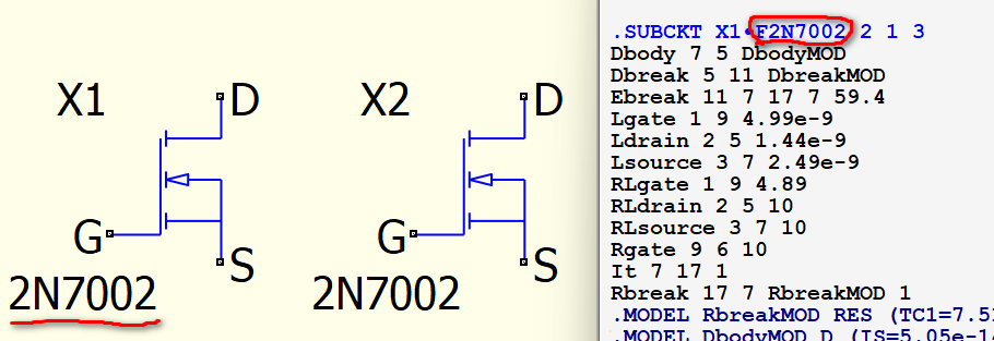
«description: Machine generated symbol for F2N7002»
«library file: |.SUBCKT F2N7002 2 1 3\nDbody 7 5 DbodyMOD\nDbreak 5 11 DbreakMOD\nEbreak 11 7 17 7 59.4\nLgate 1 9 4.99e-9\nLdrain 2 5 1.44e-9\nLsource 3 7 2.49e-9\nRLgate 1 9 4.89\nRLdrain 2 5 10\nRLsource 3 7 10\nRgate 9 6 10\nIt 7 17 1\nRbreak 17 7 RbreakMOD 1\n.MODEL RbreakMOD RES (TC1=7.51e-4 TC2=-2.05e-7)\n.MODEL DbodyMOD D (IS=5.05e-14 N=1 RS=1.42e-1 TRS1=2.1e-3 TRS2=4e-6 CJO=2.64e-11 M=0.38 VJ=0.60 TT=3.25e-7 XTI=3 EG=1.15)\n.MODEL DbreakMOD D (RS=100e-3 TRS1=1.0e-3 TRS2=1.8e-5)\nRdrain 5 16 RdrainMOD 0.82\n.MODEL RdrainMOD RES (TC1=8.4e-3 TC2=3.5e-6)\nM_BSIM3 16 6 7 7 Bsim3 W=0.033 L=2.0e-6 NRS=1\n.MODEL Bsim3 NMOS (LEVEL=7 VERSION=3.1 MOBMOD=3 CAPMOD=2 PARAMCHK=1 NQSMOD=0 TOX=1000e-10 XJ=1.4e-6 NCH=6.03e16 U0=700 VSAT=1.0e5 DROUT=1.0 DELTA=0.1 PSCBE2=0 RSH=5.09e-3 VTH0=1.937 VOFF=-0.1 NFACTOR=1.1 LINT=1.28e-7 DLC=1.28e-7 CGSO=2.2e-15 CGSL=0 CGDO=2.2e-13 CGDL=3.99e-9 CJ=0 CF=0 CKAPPA=0.1 KT1=-0.85 KT2=0 UA1=-1.52e-9 NJ=10)\n.ENDS»
«shorted pins: false»
«line (-200,120) (-200,180) 0 0 0x1000000 -1 -1»
«line (-200,30) (-200,-30) 0 0 0x1000000 -1 -1»
«line (-200,-120) (-200,-180) 0 0 0x1000000 -1 -1»
«line (-200,-150) (0,-150) 0 0 0x1000000 -1 -1»
«line (-120,0) (0,0) 0 0 0x1000000 -1 -1»
«line (0,-300) (0,0) 0 0 0x1000000 -1 -1»
«line (-200,150) (0,150) 0 0 0x1000000 -1 -1»
«line (0,150) (0,300) 0 0 0x1000000 -1 -1»
«line (-220,-200) (-220,150) 0 0 0x1000000 -1 -1»
«line (-220,-200) (-400,-200) 0 0 0x1000000 -1 -1»
«triangle (-200,0) (-120,20) (-120,-20) 0 0 0x1000000 0x2000000 -1 -1»
«text (-505,203) 1 14 0 0x1000000 -1 -1 "X1"»
«text (-503,-308) 1 13 0 0x1000000 -1 -1 "2N7002"»
«pin (0,300) (30,0) 1 7 0 0x0 -1 "D"»
«pin (-400,-200) (-30,0) 1 11 0 0x0 -1 "G"»
«pin (0,-300) (30,0) 1 7 0 0x0 -1 "S"»
»
Text for 2N7002_model_2.qsym:
ÿØÿÛ«symbol 2N7002
  «type: X»
  «description: Machine generated symbol for F2N7002»
  «library file: |.SUBCKT F2N7002 2 1 3\nDbody 7 5 DbodyMOD\nDbreak 5 11 DbreakMOD\nEbreak 11 7 17 7 59.4\nLgate 1 9 4.99e-9\nLdrain 2 5 1.44e-9\nLsource 3 7 2.49e-9\nRLgate 1 9 4.89\nRLdrain 2 5 10\nRLsource 3 7 10\nRgate 9 6 10\nIt 7 17 1\nRbreak 17 7 RbreakMOD 1\n.MODEL RbreakMOD RES (TC1=7.51e-4 TC2=-2.05e-7)\n.MODEL DbodyMOD D (IS=5.05e-14 N=1 RS=1.42e-1 TRS1=2.1e-3 TRS2=4e-6 CJO=2.64e-11 M=0.38 VJ=0.60 TT=3.25e-7 XTI=3 EG=1.15)\n.MODEL DbreakMOD D (RS=100e-3 TRS1=1.0e-3 TRS2=1.8e-5)\nRdrain 5 16 RdrainMOD 0.82\n.MODEL RdrainMOD RES (TC1=8.4e-3 TC2=3.5e-6)\nM_BSIM3 16 6 7 7 Bsim3 W=0.033 L=2.0e-6 NRS=1\n.MODEL Bsim3 NMOS (LEVEL=7 VERSION=3.1 MOBMOD=3 CAPMOD=2 PARAMCHK=1 NQSMOD=0 TOX=1000e-10 XJ=1.4e-6 NCH=6.03e16 U0=700 VSAT=1.0e5 DROUT=1.0 DELTA=0.1 PSCBE2=0 RSH=5.09e-3 VTH0=1.937 VOFF=-0.1 NFACTOR=1.1 LINT=1.28e-7 DLC=1.28e-7 CGSO=2.2e-15 CGSL=0 CGDO=2.2e-13 CGDL=3.99e-9 CJ=0 CF=0 CKAPPA=0.1 KT1=-0.85 KT2=0 UA1=-1.52e-9 NJ=10)\n.ENDS\n.SUBCKT F2N7002_Thermal TH TL\nCTHERM1 TH 6 1.04e-4\nCTHERM2 6 5 4.44e-4\nCTHERM3 5 4 6.32e-4\nCTHERM4 4 3 8.64e-4\nCTHERM5 3 2 1.12e-3\nCTHERM6 2 TL 6.02e-3\nRTHERM1 TH 6 5.20e-1\nRTHERM2 6 5 3.50e+0\nRTHERM3 5 4 1.20e+1\nRTHERM4 4 3 2.50e+1\nRTHERM5 3 2 1.24e+2\nRTHERM6 2 TL 4.60e+2\n.ENDS F2N7002_Thermal»
  «shorted pins: false»
  «line (-200,120) (-200,180) 0 0 0x1000000 -1 -1»
  «line (-200,30) (-200,-30) 0 0 0x1000000 -1 -1»
  «line (-200,-120) (-200,-180) 0 0 0x1000000 -1 -1»
  «line (-200,-150) (0,-150) 0 0 0x1000000 -1 -1»
  «line (-120,0) (0,0) 0 0 0x1000000 -1 -1»
  «line (0,-300) (0,0) 0 0 0x1000000 -1 -1»
  «line (-200,150) (0,150) 0 0 0x1000000 -1 -1»
  «line (0,150) (0,300) 0 0 0x1000000 -1 -1»
  «line (-220,-200) (-220,150) 0 0 0x1000000 -1 -1»
  «line (-220,-200) (-400,-200) 0 0 0x1000000 -1 -1»
  «triangle (-200,0) (-120,20) (-120,-20) 0 0 0x1000000 0x2000000 -1 -1»
  «text (-505,203) 1 14 0 0x1000000 -1 -1 "X1"»
  «text (-503,-308) 1 13 0 0x1000000 -1 -1 "2N7002"»
  «pin (0,300) (30,0) 1 7 0 0x0 -1 "D"»
  «pin (-400,-200) (-30,0) 1 11 0 0x0 -1 "G"»
  «pin (0,-300) (30,0) 1 7 0 0x0 -1 "S"»
»
Text for .qsch (mosfet model missing. Plug in either):
ÿØÿÛ«schematic
  «component (0,700) 0 0
    «symbol V
      «type: V»
      «description: Independent Voltage Source»
      «shorted pins: false»
      «line (0,-130) (0,-200) 0 0 0x1000000 -1 -1»
      «line (0,200) (0,130) 0 0 0x1000000 -1 -1»
      «rect (-25,77) (25,73) 0 0 0 0x1000000 0x3000000 -1 0 -1»
      «rect (-2,50) (2,100) 0 0 0 0x1000000 0x3000000 -1 0 -1»
      «rect (-25,-73) (25,-77) 0 0 0 0x1000000 0x3000000 -1 0 -1»
      «ellipse (-130,130) (130,-130) 0 0 0 0x1000000 0x1000000 -1 -1»
      «text (100,150) 1 7 0 0x1000000 -1 -1 "V1"»
      «text (100,-150) 1 7 0 0x1000000 -1 -1 "5"»
      «pin (0,200) (0,0) 1 0 0 0x0 -1 "+"»
      «pin (0,-200) (0,0) 1 0 0 0x0 -1 "-"»
    »
  »
  «component (-1600,-500) 0 0
    «symbol Vpulse
      «type: V»
      «description: Independent Voltage Source»
      «shorted pins: false»
      «line (0,-130) (0,-200) 0 0 0x1000000 -1 -1»
      «line (0,200) (0,130) 0 0 0x1000000 -1 -1»
      «line (-70,-30) (-50,-30) 0 0 0x1000000 -1 -1»
      «line (-50,-30) (-40,30) 0 0 0x1000000 -1 -1»
      «line (-40,30) (0,30) 0 0 0x1000000 -1 -1»
      «line (0,30) (10,-30) 0 0 0x1000000 -1 -1»
      «line (10,-30) (70,-30) 0 0 0x1000000 -1 -1»
      «rect (-25,77) (25,73) 0 0 0 0x1000000 0x3000000 -1 0 -1»
      «rect (-2,50) (2,100) 0 0 0 0x1000000 0x3000000 -1 0 -1»
      «rect (-25,-73) (25,-77) 0 0 0 0x1000000 0x3000000 -1 0 -1»
      «ellipse (-130,130) (130,-130) 0 0 0 0x1000000 0x1000000 -1 -1»
      «text (100,150) 1 7 0 0x1000000 -1 -1 "V3"»
      «text (100,-200) 1 7 0 0x1000000 -1 -1 "PULSE 0 4 0 1 1 1 5 1 "»
      «pin (0,200) (0,0) 1 0 0 0x0 -1 "+"»
      «pin (0,-200) (0,0) 1 0 0 0x0 -1 "-"»
    »
  »
  «net (0,500) 1 13 0 "GND"»
  «net (-1600,-700) 1 13 0 "GND"»
  «net (-300,-1000) 1 13 0 "GND"»
  «wire (0,900) (-300,900) "N01"»
  «wire (-300,900) (-300,200) "N01"»
  «wire (-700,-300) (-1600,-300) "N02"»
  «wire (-300,-400) (-300,-1000) "GND"»
  «text (-1600,-1000) 1 7 0 0x1000000 -1 -1 ".tran 5"»
»