Good morning
I wanted to create a thread to share my experience with Model Generator and compare it with others.
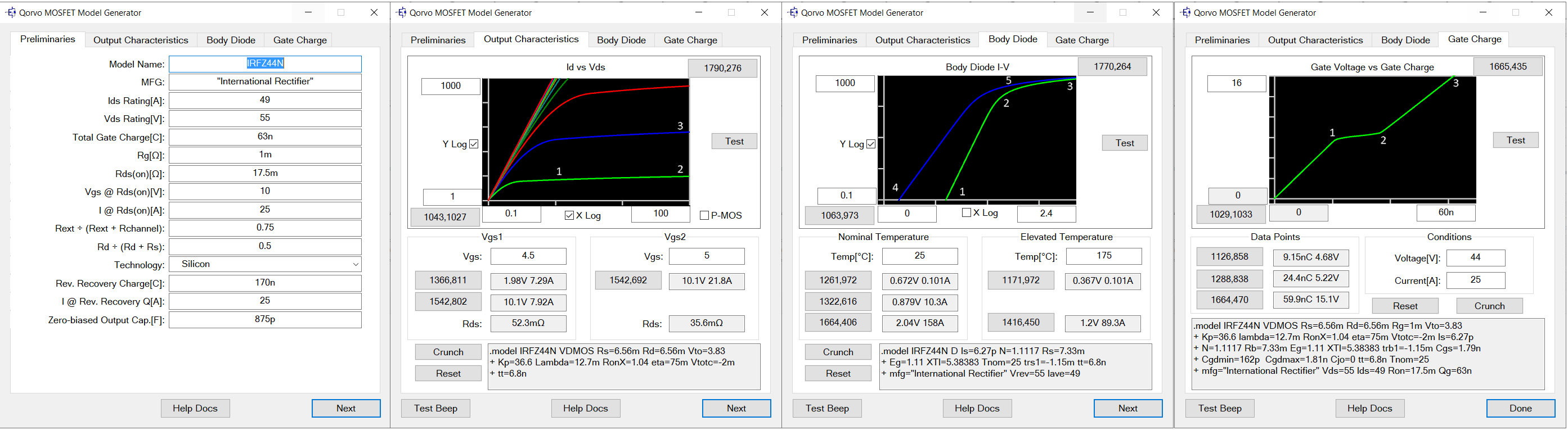
I’ve used MOSFET generator to create a model
Preliminaries:
First thing I’ve noticed was that ctrl+v (paste) shortcut doesn’t work here, however mouse leftclick+paste does. Stangely ctrl+x (cut) does work.
Second thing - I think it would be more intuitive to put some kind of border (a thick line for example) between section that is purely informational and one that has actual impact on model behaviour. I know this information is visible in Help Docs, but still.
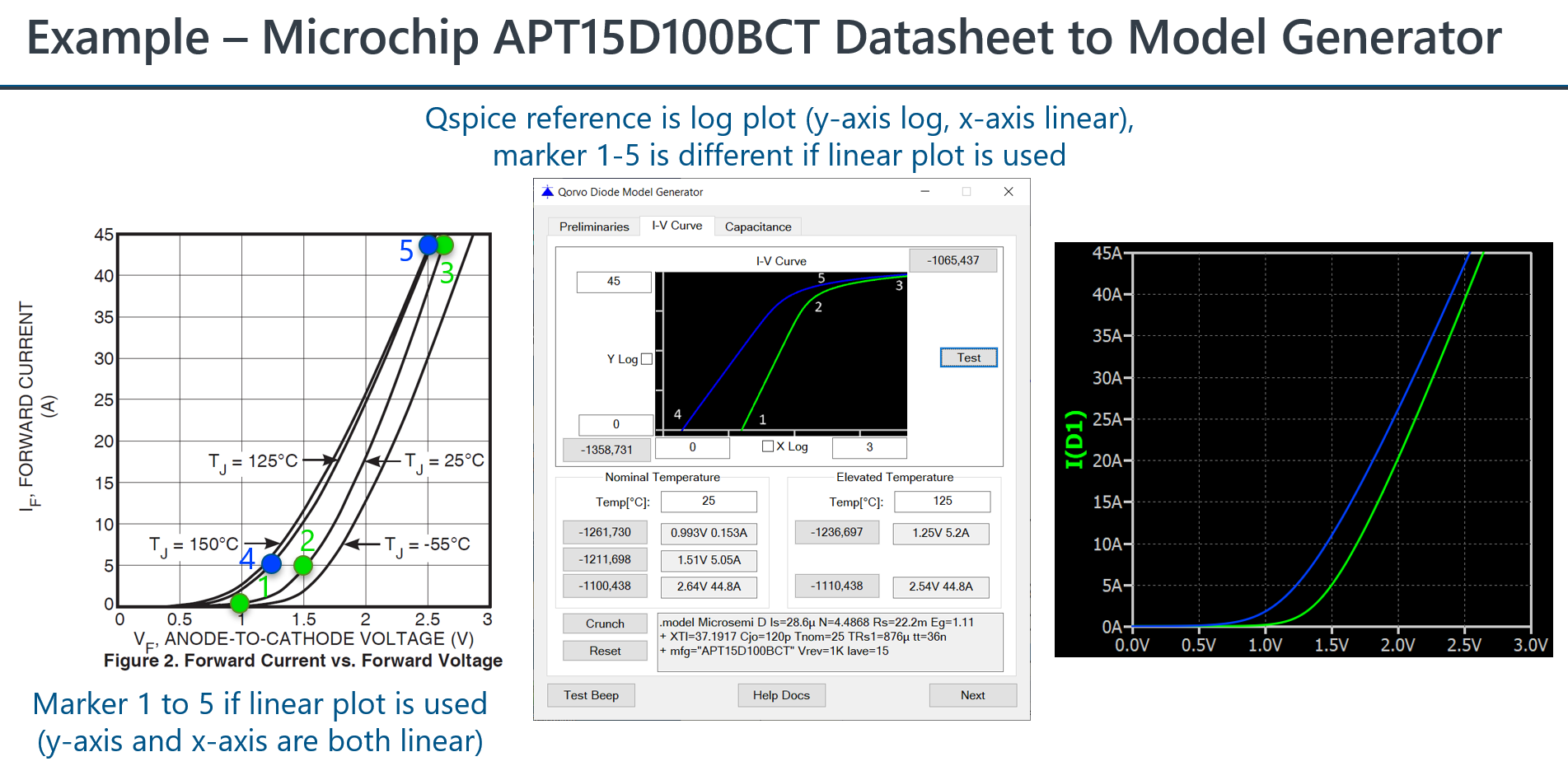
The digitize feature:
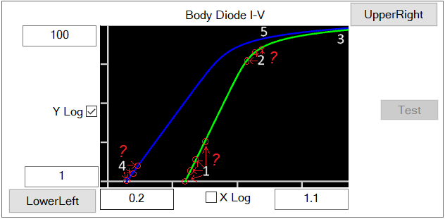
The digitizer feature is very usefull and easy to use (once accustomed). Remember to configure the plot first (set limits, logarythmic axes) BEFORE selecting any particular points from the datasheet plot. Already selected points won’t recalculate automatically if you change plot settings.
.
The thing I feel like is missing here is more direct marking of the points (placing a marker - just like in simulation waveform plot - picture attached)
and ability to manually enter the values instead of using digitizer (or to currect values acquired via digitizer).
Also I was getting some kind of redering errors throughout the process (which would appear randomly) and could be fixed by switching between tabs (picture attached - don’t mind the red annotations)
Hi Farel, thanks for your detailed notes. We’ve not formally launched the Model Generator yet, we’re still working on materials for it, we’ll go over what you’ve provided. Best, Tim
Is the model generator also accounting for Coss, Crss, Ciss?
Upon reading the model generator, there is no any way to insert these capacitance models.
Is it enough to infer these capacitance only from gate charge plot?
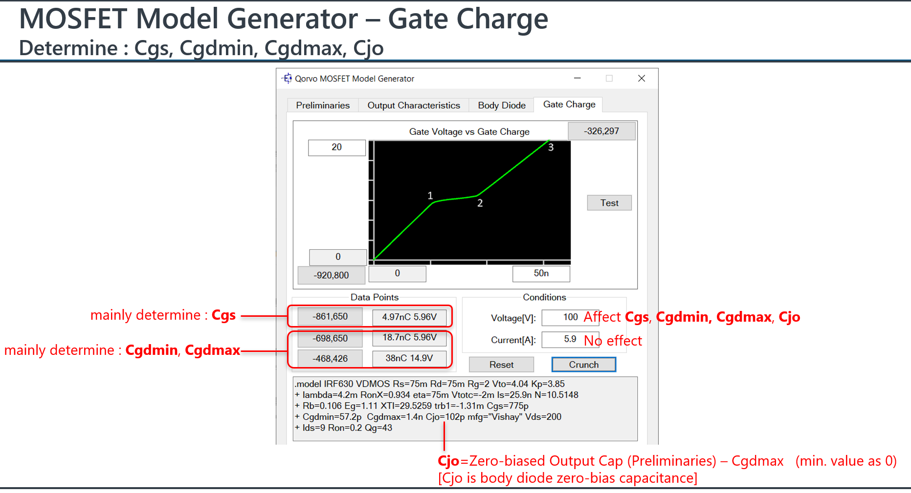
from my understanding, model parameters Cgs, Cgdmin, Cgdmax (and Cjo in its body diode) are fundamental elements of Coss, Crss and Ciss. Gate Charge characteristic actually the behavior correlates to that.
Thanks, Kelvin. Here are some notes Mike made on this:
The charge model is that of a power MOSFET: fixed Cgs, a highly nonlinear Cgd, and an output capacitance that of the body diode. While ideal for power MOSFETs, it is usually good enough for design purposes since it will accurately tell you whether or not you can turn that FET on or not. It’s a charge model that I invented and has been copied in other SPICE programs since most SPICE programs can’t simulate a power MOSFET.
Coss, Crss, and Ciss are basically capacitances of the channel. While QSPICE supports both Meyer and Yang-Chatterjee charge models for the channel of a VDMOS transistor, those are left zero by the Model Generation tool because almost all discrete MOSFETs are vertical and the charge model above is either better or at least sufficient. The exception is the concern for modeling soft switching. I might extend the device equations to model the output capacitance that changes more abruptly than a simple body diode junction capacitance.
Anyone ever encountered a datasheet that doesn’t have the gate charge characteristics start at <0,0> and how to handle it? The Gate Charge tab doesn’t allow for non-<0,0> origins.
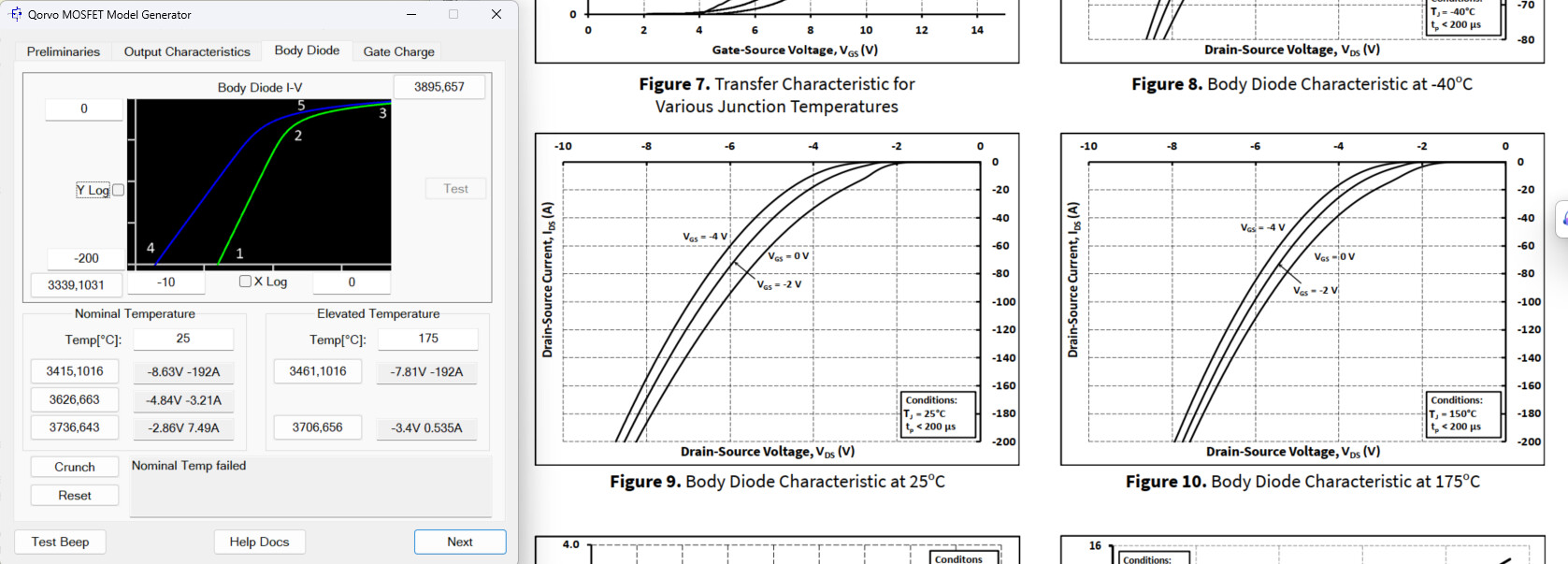
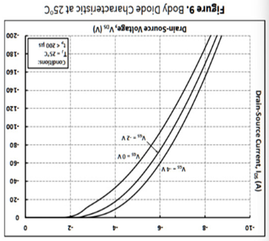
I also had another struggle with the body diode data. After performing the “the crunch”, it says nominal temp failed. Note that the axes on my datasheet are both negative and the x-axis is in terms of Vds, not Vsd. My temperature data is spread across multiple plots. Luckily, the scale of the plots are the same and so it is easy to guess where the plots would line up on the room temperature plot.
For the body diode, I believe the model generator assume y-axis as Isd and x-axis as Vsd (source-to-drain), as in general this is how a MOSFET datasheet given.
The datasheet you quote, as defined as Ids and Vds, it gives negative value. So, you should flip your graph as below but without putting negative sign.
Thanks. I thought about doing this, but I didn’t know if there was going to be a new issue due to the expected waveform of the model creator going from a curve that looks something like a natural logarithmic to an exponential growth function. Really appreciate it!
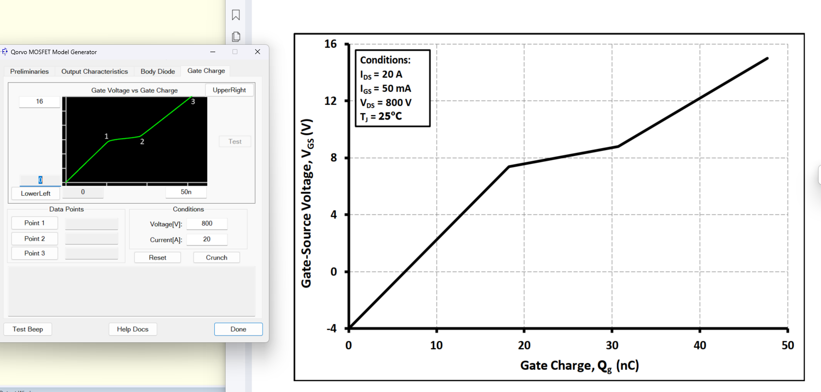
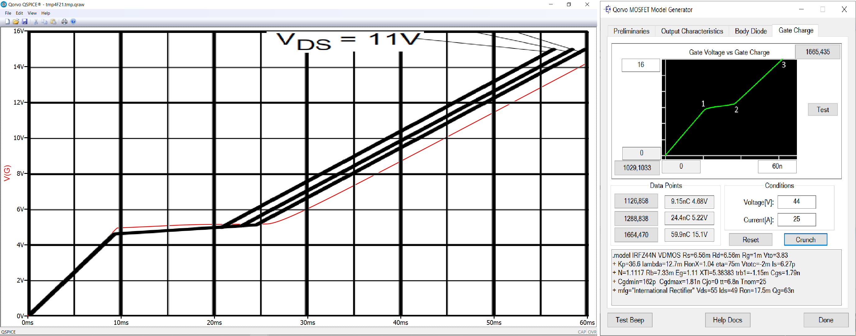
I seem to be having troubles getting the last step in Si MOSFET model generation tool to cooperate - gate voltage vs gate charge. The issue is final graph is missing selected points by noticable margin. For example here is attempt of remaking IRFZ44N by IR:
I chose this transistor just to show the problem. With another one the whole Miller platou region (points 2. and 3.) would constantly end up lower (at lower voltage) than what datasheet was describing despite selecting corrent points.
Do previous entries (Preliminaries, Output Capacitance, Body Diode) have any impact on graph created in this section ?
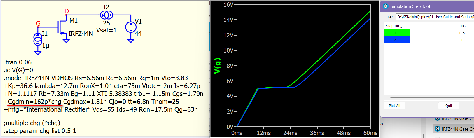
I’m unsure if I interpreted your message correctly, but it appears that you want to shift the gate charge region [2,3] to the left. In a reverse engineering analysis, the gate charge section in the model generator is responsible for computing MOSFET model parameters such as Cgs, Cgdmin, Cgsmax, and Cjo. The model parameter associated with the region [2,3] is Cgdmin and Cgdmax. Therefore, if specific details of your results are crucial, you may consider fine-tuning the model parameters. Here is an example of adjusting Cgdmin by -50%.
Thank you KSKelvin
I guess this is the way to correct the model. My question is why did the digitized model fail to meet the required points (2. and 3.) in the first place ?
Could it be the parameter estimation part of the model generator is in need of some fine tuning ?
Also regarding the issue of Miller Platou happening at lower gate voltage than desired - I was able mitigate the issue by adjusting Cgdmin and Vto.
After viewing Mike’s video, and starting through the tool, this is a tremendous time and general accuracy improvement - thanks @Engelhardt.
My initial experience with this tool is to generate a zener diode model. While there is a capacitance curve provided in the datasheet for the device, there is no I-V data. How problematic is this, so long as the Preliminaries page is filled out as best as possible: Technology, Zener Voltage, Current and Impedance?