It does not have holes to fix them with screws in a mechanical structure. Since the pins below are not used… can I use them for that? I’m not going to solder them. Do you think it can cause something to be damaged or what?
I wouldn’t put screws through those holes. They will be too small for anything but the smallest screws and the risk of the screw head causing shorts to the components and other traces is too great.
I’d either secure it by soldering pins between this board and the rest of your system (probably not a realistic option for your application) or by gluing something to the back of the board and using that to hold it. I’ve even used Velcro tape to secure things like this in the past, convenient but not the most repeatable method.
Just make sure you keep everything below the line of the antenna.
The simplest thing is to stick it with a double-sided tape, but it would not look good.
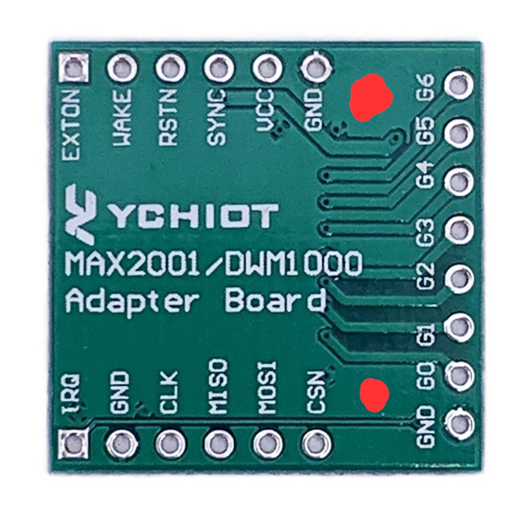
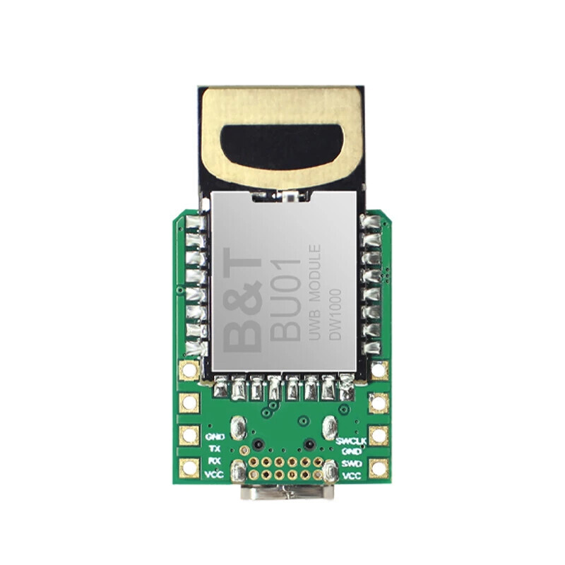
Are you sure that using the lower pins (without connecting them to the module) will cause a short? (The lower pin are: GND and the lower pin G6 of the adapter. Without attaching it to the DWM1000 module with tin).
The screws are m3, I estimate that they do fit in the holes that the adapter already has.
@AndyA, my problem is that I have to fix it because they will be anchors in a robot that will move, if the anchors move the whole system is damaged, and with tape or glue it will not be 100% fixed (unlike screws).
I wanted to do the following:
With a felling make two holes (the red points in the image). Problem: I can damage it.
Do not solder to the DMW1000 module and use pins G0 and G6. Problem: small pins.
What do you advise me? (my product arrives tomorrow and I would like to know what I should do).
I don’t know if anyone sells anything to adjust/mount/fix test PCB.
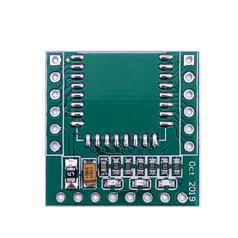
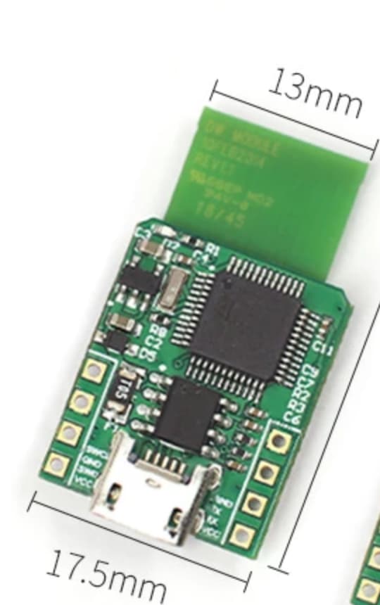
Where you marked the module in red looks like it would hit parts on the other side.
Of the two I’d go with soldering the pins but put some Kapton tape down under those pins on the module because even if you don’t solder the connections the pads will be resting on each other and so make contact.
And then place some sort of mechanical support under the back of the module, a single row of soldered pins would allow the module to wobble a bit if there is no other support.
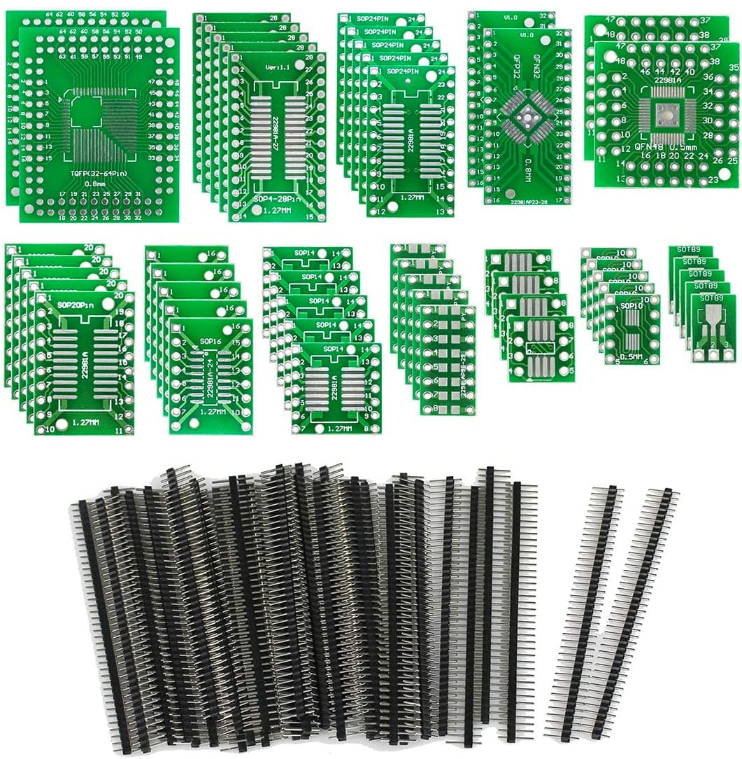
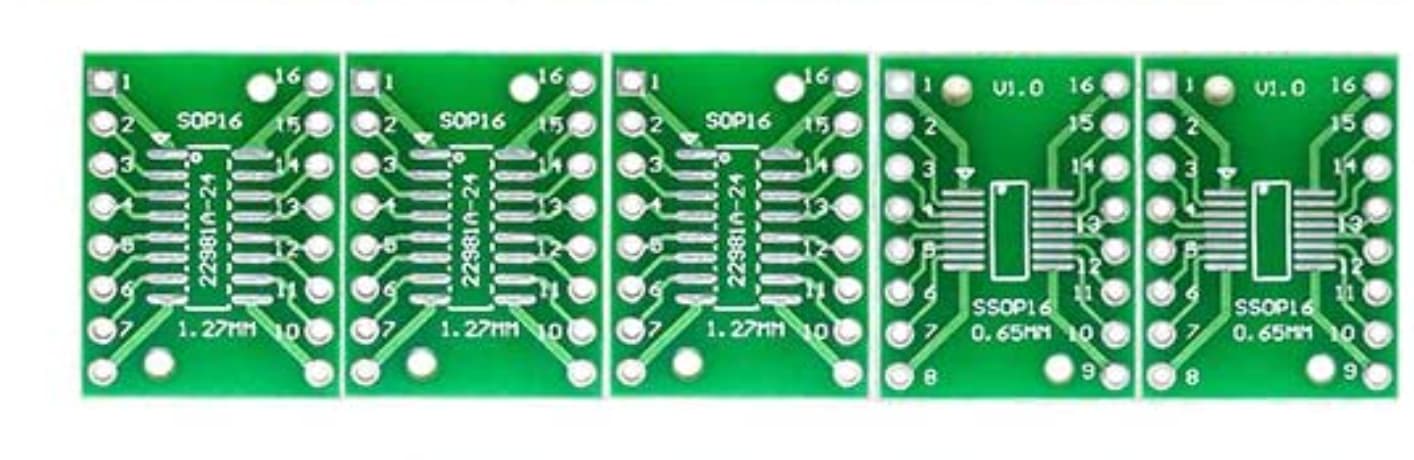
You need to use an adaptor that is designed specifically for the DWM1000. You need something with no copper (and ideally no board) under the antenna and with connections on 3 sides. That’s not a standard part.
So while the pin spacing is one of the standard ones (there are several SMD standards, 0.1" (2.54mm), 0.05" (1.27mm), 0.025" (0.65mm), 1 mm, 0.8 mm, 0.5 mm) the exact layout requirement isn’t standard.
You’re falling into the same trap as you did with how to connect the modules up and are over thinking this.
Don’t worry about getting it perfect, worry about coming up with something that is easy to do and looks like it will work. Once you get to that point stop.
It’s ok to make small incremental improvements on a decision but don’t go backwards and start looking at new completely different pcbs. You’ve spend a week trying to decide how to attach a 1" square piece of fiberglass to something. If you carry on at this speed you’re not going to ever build anything.
Glue / velcro it in place (or try screws on a board without a DWM1000 fitted and check it very carefully, just try something) and if that looks like it’ll work for now then get on with building the rest of your system. Your range measurements are going to be +/- 5 cm anyway so mm accurate mounting isn’t necessary.
Only worry about coming up with something more solid if this proves unreliable. Until that happens you’ve got plenty of other work to do.
But, as I am still an inexperienced, I ask you for advice.
The one with the Aliexpress link, what do you think?
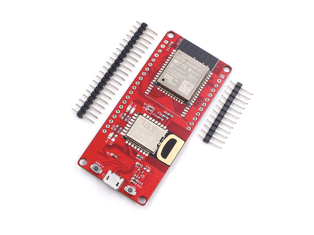
If I buy 1 of those, will it be compatible with the ones I already have integrated with ESP32? (As I told you before, apparently they are the same dw1000 bu modules)
Will I have to upload the code with Arduino or is it not possible? (I asked the seller, but still no response. Your opinion is valuable to me, after all your help, what do you think?)